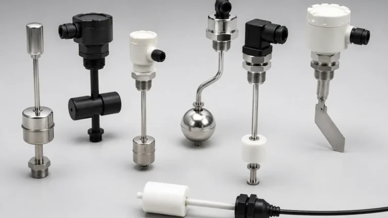
4-way Switches
4-way Switches
In the landscape of industrial automation and fluid management, the ability to monitor multiple discrete levels within a single vessel is critical for safety, efficiency, and process control. While simple level detection often relies on a single setpoint, complex applications—such as those requiring redundant alarms and automated pump control—frequently utilize multi-point configurations. Among these, 4-way switches (or quad-point level switches) stand as a standard for comprehensive tank management. These instruments provide four independent switching signals, typically representing Low-Low, Low, High, and High-High levels, allowing engineers to manage complex logic cycles within a single installation point.
Understanding the Measurement Principles
Before selecting a specific technology for 4-way switching, it is essential to understand the physical principles that govern how these devices detect the presence or absence of a medium. In industrial level measurement, "4-way" refers to the number of discrete output signals generated by the device as the material level crosses specific thresholds.
Magnetic Float Technology
The most common principle for multi-point Level Switches is the magnetic float. This design utilizes a hollow float containing an internal magnet that slides up and down a stationary stem. Inside the stem, reed switches are positioned at precise intervals (the four setpoints). As the float rises or falls with the liquid level, the magnetic field actuates the reed switches, opening or closing the electrical circuit. This method is highly reliable for clean liquids and requires no external power to operate the primary sensing element.
Conductivity Probes
For conductive liquids, such as water or acids, conductivity probes are often employed. A 4-way conductivity switch consists of four stainless steel electrodes of varying lengths, plus a reference ground probe. When the liquid touches a probe, a low-voltage circuit is completed between that probe and the ground. This technology is valued for its lack of moving parts, making it suitable for applications with high vibration or turbulence.
Ultrasonic and Optical Point Detection
In applications where contact with the medium must be minimized or where the fluid is highly viscous, ultrasonic or optical gap switches may be used. While these are often single-point devices, they can be manifolded or integrated into a multi-sensor array to provide 4-way switching logic. These sensors rely on the attenuation of ultrasonic waves or the refraction of light when the sensing tip is submerged.
The Logic of 4-Way Level Control
Integrating 4-way switches into a control system (such as a PLC or DCS) allows for a sophisticated management strategy. The four points are generally assigned the following functions:
1. Level 1: Low-Low (L-L): This is the ultimate safety threshold. It is used to trigger an emergency shutdown of pumps to prevent dry running, which can cause catastrophic seal failure and motor burnout. It also acts as a primary alarm for inventory depletion.
2. Level 2: Low (L): This point typically functions as the "Pump Start" signal in a tank-fill application or the "Pump Stop" signal in a tank-empty application. It ensures the process remains within a nominal operating range.
3. Level 3: High (H): The counterpart to the Low level, this point signals the system to stop filling or start emptying. The distance between the Low and High points defines the "operating deadband," preventing the pump from cycling too frequently (chattering).
4. Level 4: High-High (H-H): This is the overfill prevention setpoint. If the level reaches this point, it indicates a failure in the primary control loop (e.g., a stuck valve or a failed pump). The H-H switch triggers an audible alarm and may mechanically interlock with an inlet valve to stop flow immediately.
Practical Selection Criteria
Choosing the correct 4-way switch requires an evaluation of the physical and chemical properties of the process medium, as well as the environmental conditions of the installation site.
| Criteria | Considerations |
| :— | :— |
| Medium Density | For float-based 4-way switches, the liquid density must be higher than the float's displacement capability. Standard floats typically require a minimum density of 0.7 g/cm³ (700 kg/m³). |
| Chemical Compatibility | The wetted parts (stem, floats, or probes) must resist corrosion. Common materials include 316L Stainless Steel, PP, PVC, and PVDF. |
| Pressure and Temperature | High-pressure vessels (above 10 bar) require specialized reinforced floats. High-temperature applications (above 120°C) may require heat-dissipating fins or ceramic internals. |
| Viscosity and Coating | Highly viscous liquids or those that crystallize can impede the movement of floats. In these cases, conductivity or non-contact sensors are preferred. |
| Output Type | Determine if the system requires SPST (Single Pole Single Throw) or SPDT (Single Pole Double Throw) contacts. SPDT is often preferred for 4-way switches to provide both normally open and normally closed options for each point. |
Installation Considerations and Best Practices
Proper installation is paramount to the longevity and accuracy of 4-way level switches. Engineering teams should adhere to the following guidelines:
* Vertical Alignment: For float-based switches, the stem must be installed within 30° of vertical. Excessive tilting can cause friction between the float and the stem, leading to sticking or delayed responses.
* Turbulence Protection: If the tank features an agitator or a high-velocity inlet pipe, the switch should be installed inside a stilling well. A stilling well is a perforated pipe (typically 50mm to 100mm in diameter) that surrounds the switch, providing a calm liquid surface for accurate measurement.
* Wiring and Interference: Multi-point switches involve multiple wire pairs. Using shielded cables is recommended to prevent electromagnetic interference (EMI) from nearby high-voltage pump motors from triggering false signals.
* Mounting Location: Ensure there is sufficient overhead clearance to remove the entire assembly for maintenance. For a 4-way switch with a 2-meter stem, at least 2.1 meters of clearance is required above the mounting flange.
Limitations of 4-Way Switches
While highly effective, 4-way switches have inherent limitations that must be managed:
1. Discrete vs. Continuous: 4-way switches provide point-level data only. They cannot inform the operator of the exact level between setpoints (e.g., if the tank is at 45% or 55%). If continuous monitoring is required, a radar or ultrasonic transmitter should be used alongside the switches.
2. Mechanical Wear: Any device with moving parts, such as a magnetic float switch, is subject to mechanical wear over millions of cycles. Regular inspection of the float's buoyancy and the integrity of the reed switches is necessary.
3. Build-up: In wastewater or slurry applications, material can build up on the stem or probes. This "bridging" can cause a 4-way switch to remain in the "on" position even after the liquid level has dropped.
Frequently Asked Questions (FAQ)
Q: Can the setpoints on a 4-way switch be adjusted after installation?
A: This depends on the design. In many magnetic float switches, the reed switches are fixed inside the stem with epoxy and cannot be moved. However, some modular designs allow the user to slide the internal switch elements to new positions. Conductivity probes can often be trimmed to length to adjust setpoints.
Q: What is the maximum length for a 4-way level switch stem?
A: Standard industrial lengths typically range from 100mm to 3000mm (3 meters). For lengths exceeding 3 meters, the stem may require additional bracing or a larger diameter to prevent bending under the weight of the fluid's movement.
Q: Is it possible to have more than 4 points on a single switch?
A: Yes. Many manufacturers offer custom configurations with up to 6 or 7 points, depending on the stem length and the size of the floats. However, 4 points remain the industry standard for most pump control and alarm logic.
Q: How do I test a 4-way switch without filling the tank?
A: For float switches, the most reliable method is a manual lift test. If the tank is empty and safe to enter (or if the switch is removed), manually slide the float past the setpoints and verify the signal change at the control panel. For conductivity switches, a jumper wire can be used to simulate the liquid's path to ground.
Conclusion
4-way switches represent a robust and cost-effective solution for multi-stage level control in industrial environments. By providing four distinct signals within a single process connection, they simplify wiring and reduce the number of tank penetrations required. Whether utilizing magnetic float technology or conductivity probes, understanding the specific requirements of the medium and the logic of the control loop is essential for a successful implementation. When properly selected and installed, these devices provide a critical layer of protection and automation for water treatment, chemical processing, and oil and gas storage facilities worldwide.