What Is R on Switch
What Is R on Switch
In industrial automation and process control, the nomenclature used on terminal blocks and wiring diagrams is critical for ensuring the safe and accurate installation of instrumentation. When technicians and engineers encounter the label "R" on an industrial switch—specifically within the context of Level Switches—it typically refers to one of three technical designations: Relay, Resistance (or Resistor), or Reset.
Understanding the specific function of the "R" terminal is essential for integrating level measurement devices into a wider control system, such as a PLC (Programmable Logic Controller) or a DCS (Distributed Control System). This article explores the various meanings of "R" on a switch, the measurement principles of level switches, and practical selection and installation guidelines for industrial applications.
The Technical Meanings of "R" on Industrial Switches
Depending on the manufacturer and the specific technology of the level switch, the "R" marking serves different roles. Below are the most common interpretations in a B2B industrial context.
1. Relay Output (R, R1, R2)
The most frequent use of "R" on a level switch terminal block is to designate the Relay output. Level switches are point-level detection devices; when the material (liquid or solid) reaches a specific height, the switch changes state. This state change is often communicated via a mechanical relay.
* R (Common): Sometimes used to denote the common terminal of a relay contact.
* R1/R2: In dual-point level switches or switches with redundant outputs, R1 and R2 represent the first and second relay channels.
* Logic: When the sensor detects the media, the relay energizes or de-energizes, closing or opening the circuit to trigger an alarm or start a pump.
2. Resistance and NAMUR Standards (R)
In hazardous area applications or systems using NAMUR (EN 60947-5-6) standards, "R" may refer to an internal Resistor or a resistance-based output signal.
* Line Monitoring: Many modern level switches include internal resistors to allow the control system to distinguish between a "Switch Open" state and a "Wire Break" (infinite resistance) or a "Short Circuit" (zero resistance).
* NAMUR Signals: These switches operate on a variable resistance principle, where the current flow changes (typically between 1mA and 2.1mA) based on the proximity of the target media.
3. Reset Function (R or RST)
In safety-critical applications, such as high-level spill prevention, a level switch may feature a latching relay. Once the high-level alarm is triggered, the switch remains in the alarm state even if the level drops.
* Manual Reset: The "R" terminal is used to connect an external reset button. Shorting this terminal to a common ground or applying a pulse resets the switch to its normal operating state after the fault or high-level condition has been cleared.
Measurement Principles of Common Level Switches
Before selecting a switch or interpreting its wiring, it is important to understand how different technologies detect the presence of media. Each principle dictates how the output (the "R" terminal) will behave.
Tuning Fork (Vibrating) Level Switches
Vibrating level switches utilize a piezoelectric crystal to energize a tuning fork at its natural resonance frequency. When the fork is submerged in a liquid or covered by solids, the frequency changes or the vibration is dampened. The internal electronics detect this shift and toggle the relay (R) output. These are highly reliable as they are not affected by flow, turbulence, bubbles, or foam.
Capacitance Level Switches
These switches treat the probe and the tank wall (or a reference electrode) as two plates of a capacitor. As the level rises, the dielectric constant changes because the process media replaces the air/gas between the electrodes. This change in capacitance is converted into a switching signal. Capacitance switches are ideal for powders and granulated solids but require calibration for the specific dielectric constant of the material.
Float Level Switches
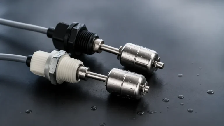
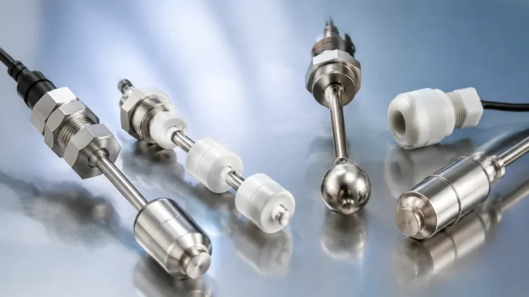
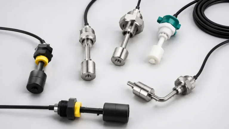
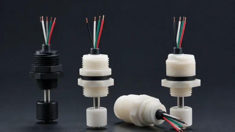
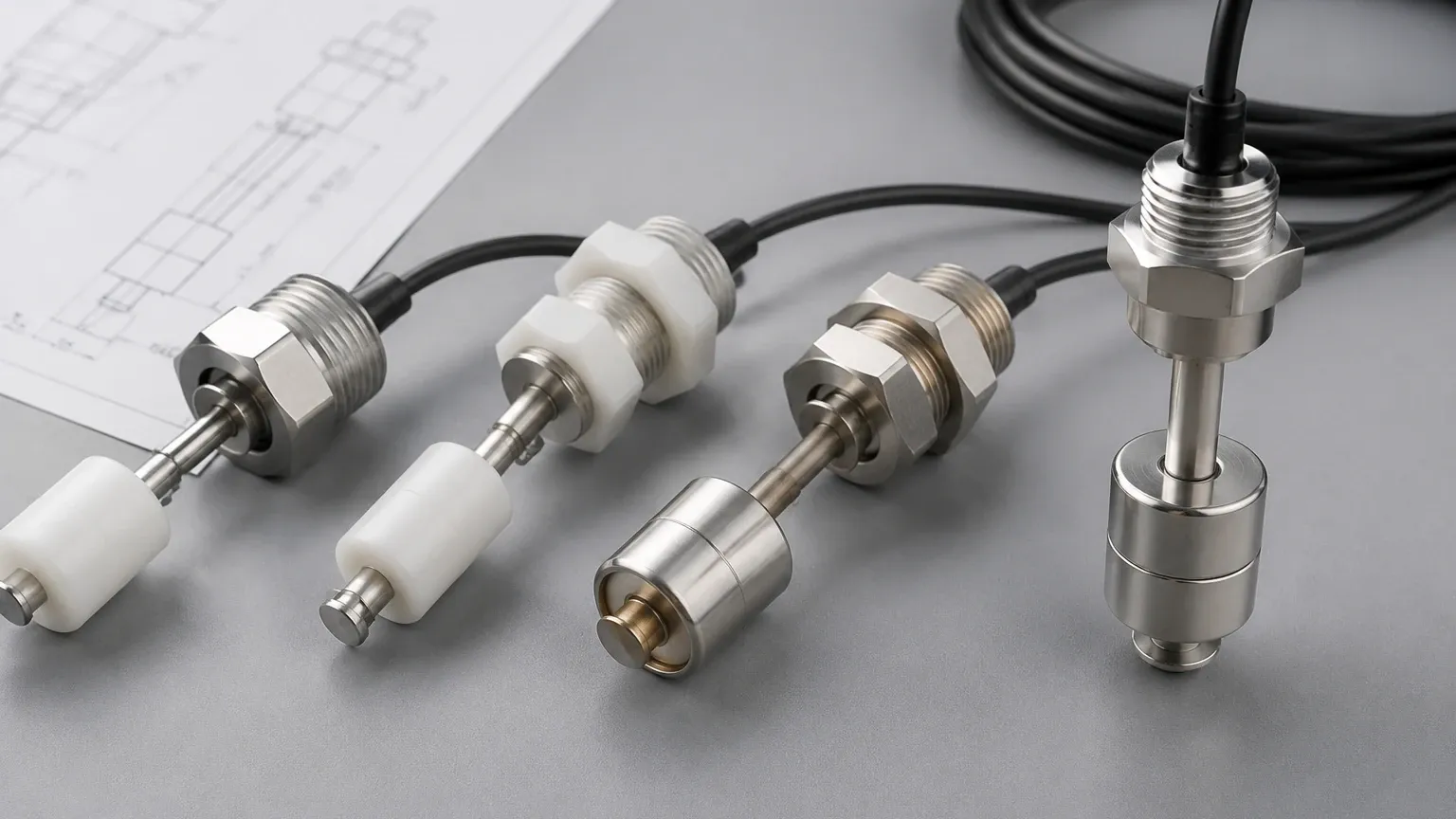
The simplest form of level detection, float switches use a magnetic float that rises and falls with the liquid level. As the float moves, it actuates a reed switch or a microswitch inside the stem. The "R" terminal here is almost always a direct connection to the mechanical switch contacts.
Selection Criteria for Level Switches
Choosing the right instrument requires evaluating the physical properties of the media and the environmental conditions of the installation site. The following table provides a comparison of common technologies.
| Technology | Media Type | Temp. Range | Pressure Range | Key Advantage |
| :— | :— | :— | :— | :— |
| Vibrating Fork | Liquids/Solids | -50°C to 150°C | Up to 40 bar | Maintenance-free; no calibration needed. |
| Capacitance | Liquids/Solids | -40°C to 200°C | Up to 25 bar | Good for sticky or viscous materials. |
| Float | Clean Liquids | -10°C to 120°C | Up to 10 bar | Low cost; simple mechanical operation. |
| Ultrasonic | Liquids | -40°C to 90°C | Up to 3 bar | Non-contact detection. |
Installation and Wiring Considerations
When wiring the "R" terminal on a switch, several engineering factors must be considered to prevent equipment failure or safety hazards.
Contact Ratings and Inductive Loads
If the "R" terminal represents a relay contact, it is vital to check the maximum voltage and current ratings. Industrial level switches typically support 250V AC / 3A or 30V DC / 5A.
* Inductive Loads: If the switch is directly controlling a motor or a solenoid valve, the inductive kickback can weld the relay contacts together. In these cases, an external interposing relay or a snubber circuit (RC circuit) should be used to protect the switch.
Fail-Safe Modes (High/Low)
Level switches usually feature a selectable fail-safe mode.
* FSH (Fail-Safe High): The relay is energized when the level is low and de-energizes when the level is high or power is lost. This is used for overfill prevention.
* FSL (Fail-Safe Low): The relay is energized when the level is high and de-energizes when the level is low. This is used for dry-run protection of pumps.
Cable Selection and Shielding
For switches using the "R" terminal for resistance-based signaling (like NAMUR), shielded twisted-pair cabling is recommended. This prevents electromagnetic interference (EMI) from high-power cables from inducing false signals in the low-voltage control loop.
Limitations and Safety Standards
While level switches are robust, they have limitations that must be addressed during the design phase:
1. Build-up: Some sensors, like capacitance probes, can give false readings if the material coats the probe. In such cases, switches with "active shield" technology should be used.
2. Turbulence: In tanks with heavy agitation, float switches may bounce, leading to "chattering" of the relay. A time delay (typically 0.5 to 3 seconds) should be configured on the switch or in the PLC logic.
3. Hazardous Areas: If the switch is installed in a zone with explosive gases or dust, it must be ATEX or IECEx certified. The "R" terminal in these instances must be connected via an intrinsically safe (IS) barrier.
Frequently Asked Questions (FAQ)
What is R on switch in a 3-wire DC configuration?
In a 3-wire DC NPN or PNP switch, "R" is rarely used as a terminal label. Instead, you will see L+, L-, and Out. However, if an "R" is present, it may refer to the Load Resistor required for certain types of PLC inputs to correctly sense the voltage drop.
Can I use the R terminal to drive a pump directly?
Generally, no. Most Level Switches have small internal relays designed for signaling, not power distribution. Direct connection to a pump motor can cause the contacts to overheat and fail. Always use the switch to trigger a heavy-duty contactor.
How do I test if the R terminal is functioning?
Using a multimeter set to Resistance (Ohms) or Continuity mode, check the state of the R terminal relative to the Common (C) terminal while manually actuating the switch (e.g., by immersing a tuning fork in water or lifting a float). You should see the resistance move from infinity to near-zero (or vice-versa).
Does the "R" terminal require a specific wire color?
While there is no universal international standard for terminal "R," industrial best practices often use red for control circuits or orange for circuits that may remain energized when the main power is disconnected. Always refer to the manufacturer’s specific wiring diagram provided with the device.
Conclusion
Identifying "what is r on switch" is a fundamental step in industrial electrical integration. Whether it represents a relay output for alarm signaling, a resistor for line monitoring, or a reset terminal for safety latching, the correct application of this terminal ensures the reliability of the level measurement system. By selecting the appropriate measurement principle—be it vibrating fork, capacitance, or ultrasonic—and adhering to strict installation guidelines regarding load protection and fail-safe logic, engineers can maintain high safety standards and operational efficiency in water treatment, chemical processing, and oil and gas applications.