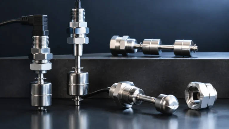
Y Limit Switch
Y Limit Switch
In the landscape of industrial automation and process control, the term "Y limit switch" typically refers to a precision sensing device used to define the boundaries of motion along a vertical or secondary axis, or as a critical feedback component in Y-type valve assemblies and material handling systems. Within the broader context of fluid and solid management, these devices function as essential Level Switches that trigger alarms or control actions when a substance reaches a predetermined threshold.
Reliable level detection is the cornerstone of operational safety. Whether preventing a tank overflow or ensuring a pump does not run dry, the integration of limit switches provides a binary (on/off) signal that is fundamental to automated logic controllers. This guide explores the technical principles, selection criteria, and installation best practices for limit switches used in industrial level and motion applications.
Understanding the Principles of Limit Detection
Before selecting a Y limit switch or any level-based limit device, it is essential to understand the underlying physical principles that allow these sensors to detect the presence or absence of a medium or a mechanical component.
Mechanical Actuation
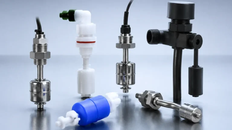
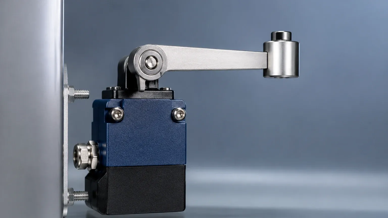
Traditional limit switches rely on physical contact. An actuator—such as a lever, roller, or plunger—is moved by the target object (e.g., a rising float or a moving machine part). This movement shifts internal electrical contacts to open or close a circuit. These are valued for their simplicity and high current-carrying capacity.
Vibrating Fork Technology
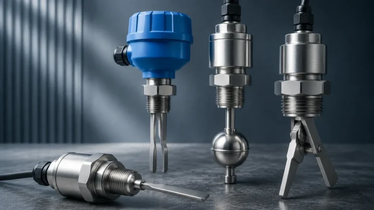
Often used as a point level limit switch, this technology involves a tuning fork-shaped sensor that vibrates at its natural resonant frequency in air. When the fork is submerged in a liquid or solid, the frequency changes. The internal electronics detect this shift and switch the output state. This method is highly resistant to changes in pressure, temperature, and conductivity.
Inductive and Capacitive Sensing
Non-contact limit switches use electromagnetic or electrostatic fields. An inductive Y limit switch detects metallic objects, while a capacitive version can detect almost any material, including liquids, plastics, and grains, by measuring the change in capacitance as the target enters the sensing field.
The Role of Level Switches in Industrial Safety
While a Y limit switch might define the physical travel of a gantry or valve, its logic is mirrored in level switches used for point detection. In process industries, these switches serve as the final line of defense.
1. Overfill Prevention: High-level limit switches are installed at the top of vessels. If the primary level transmitter fails, the limit switch provides a redundant signal to shut off inlet valves.
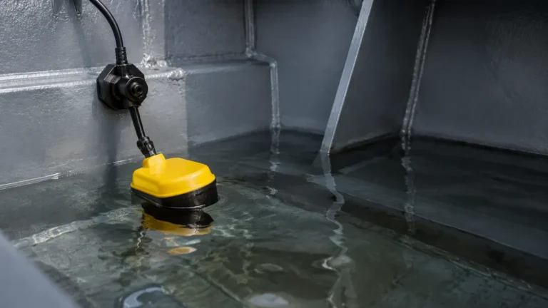
2. Dry-Run Protection: In pumping stations, a low-level limit switch ensures that the pump stops before the liquid level drops below the intake, preventing cavitation and mechanical damage.
3. Interface Detection: Specialized switches can distinguish between two different liquids (such as oil and water), allowing for the automated separation of phases.
For engineers looking to implement these safety layers, Welk offers a range of robust Level Switches designed for high-precision industrial environments.
Key Evaluation Criteria for Selection
Selecting the correct Y limit switch or level limit device requires a thorough analysis of the application environment. Using the wrong technology can lead to false triggers or premature sensor failure.
1. Media Characteristics
The physical properties of the substance being measured are paramount. For example, highly viscous liquids may stick to mechanical floats, while corrosive chemicals require specialized housing materials like PTFE (Polytetrafluoroethylene) or 316L Stainless Steel.
2. Operating Conditions
* Temperature: Standard switches may operate up to 80°C (176°F), but high-temperature variants are required for steam or molten applications, often rated up to 250°C (482°F).
* Pressure: In pressurized reactors, the switch must withstand the vessel's internal pressure, which can exceed 40 bar (580 psi) in heavy industrial settings.
3. Electrical Requirements
Engineers must confirm whether the system requires a Simple Device (like a dry contact switch) or an electronic output (PNP/NPN). Furthermore, in hazardous areas where explosive gases or dust are present, the switch must carry ATEX or IECEx intrinsic safety certifications.
Comparison of Limit Switching Technologies
The following table provides a comparison of common technologies used for limit detection in industrial level applications.
| Technology | Best For | Advantages | Limitations |
| :— | :— | :— | :— |
| Mechanical Float | Clean liquids, water tanks | Low cost, no power required | Prone to fouling, moving parts wear out |
| Vibrating Fork | Powders, granulates, liquids | High reliability, no calibration | Not suitable for very high-viscosity media |
| Capacitance | Acids, alkalis, interfaces | No moving parts, compact | Sensitive to material buildup on probe |
| Ultrasonic Gap | Non-aerated liquids | High precision, fast response | Affected by foam or heavy aeration |
| Rotary Paddle | Bulk solids, grains | Robust for heavy materials | Mechanical wear in abrasive environments |
Installation Considerations and Best Practices
Correct installation of a Y limit switch or level sensor is critical to its longevity and accuracy. Even the most advanced sensor will fail if mounted incorrectly.
Mounting Orientation
Limit switches can be mounted horizontally through the side of a tank or vertically from the top. For Y-axis motion limit switches, ensure the actuator is aligned with the direction of travel to prevent side-loading, which can bend the lever or damage the internal seals.
Cable Entry and Sealing
Always point cable entries downward to prevent moisture from traveling along the cable and into the housing (the "drip loop" principle). Use appropriate cable glands to maintain the IP67 or IP68 ingress protection rating. In outdoor installations, a sunshade can prevent UV degradation of plastic components and reduce internal heat buildup.
Avoiding Turbulence and Dead Zones
In level applications, do not install a switch directly in the path of the filling stream. The turbulence can cause "chatter" (rapid switching), which wears out relays and confuses control systems. If the tank has an agitator, ensure the switch is positioned away from the blades and any resulting vortex.
Limitations and Common Risks
While Y limit switches and level switches are highly reliable, they are not infallible. Awareness of their limitations is necessary for system design.
* Material Buildup: In applications involving sticky substances (like wastewater or syrups), material can accumulate on the sensor. This may cause a "bridging" effect where the switch remains in the "on" state even after the level has dropped.
* Vibration: Excessive mechanical vibration in the mounting structure can cause false trips in mechanical or vibrating fork switches. In such cases, damped mountings or non-contact ultrasonic switches may be preferred.
* Coating and Scaling: In hard water applications, calcium scaling can encrust a float or probe, increasing its mass and changing its switching point.
Frequently Asked Questions (FAQ)
Q: What is the difference between a limit switch and a level switch?
A: A limit switch is a general term for any device that detects when an object has reached a specific limit of travel. A level switch is a specific type of limit switch used to detect the limit of a liquid or solid level within a container.
Q: Can a Y limit switch be used in explosive environments?
A: Yes, provided it is rated for hazardous locations. You must check for EX-proof or intrinsically safe ratings (such as Class I, Div 1) before installation in such areas.
Q: How do I test if my limit switch is functioning correctly?
A: For mechanical switches, use a multimeter to check continuity across the contacts while manually actuating the arm. For electronic level switches, most modern units (like those from Welk) include a local LED indicator that changes color when the sensor is triggered.
Q: What does SPDT and DPDT mean in the context of these switches?
A: SPDT (Single Pole Double Throw) means the switch can control one circuit but has two options for the output (normally open or normally closed). DPDT (Double Pole Double Throw) is essentially two SPDT switches in one, allowing the device to control two separate circuits simultaneously for redundancy or dual-signal purposes.
Conclusion
The Y limit switch, whether acting as a mechanical stop in a positioning system or as a point-level sensor in a chemical reactor, is a vital component of modern industrial logic. By understanding the specific demands of your media and environment—and by selecting high-quality Level Switches—you can ensure the safety and efficiency of your operations. For complex applications, always consult with a technical specialist to confirm that the chosen switching technology aligns with your specific process parameters and safety requirements.