4 Lead Switch
4 Lead Switch
In the landscape of industrial automation and process control, point-level detection remains a cornerstone of safety and efficiency. Among the various configurations available to engineers, the 4 lead switch represents a specific wiring and functional category often utilized in complex level control systems. Whether used for redundancy, dual-level monitoring, or specific interlocking logic, understanding the electrical and mechanical characteristics of Level Switches is essential for ensuring system reliability.
This guide explores the technical principles of level switches, the specific utility of 4-lead configurations, and the practical considerations required for selection and installation in industrial environments.
Principles of Level Measurement
Before delving into wiring configurations, it is necessary to understand how level switches function. Unlike continuous level transmitters (such as radar or ultrasonic sensors) that provide a constant data stream of the liquid level, a level switch is a discrete device. It provides an "on/off" or "open/closed" signal when the process material reaches a specific height.
Mechanical and Magnetic Actuation
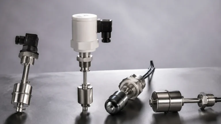
The most common principle for a 4 lead switch in liquid applications is magnetic buoyancy. A float containing an internal magnet moves along a stem as the liquid level rises or falls. Inside the stem, a hermetically sealed reed switch is positioned at a predetermined set point. When the float's magnetic field aligns with the reed switch, the contact leaves change state (closing or opening).
Other principles include:
* Conductive: Uses the conductivity of the liquid to bridge the gap between electrodes.
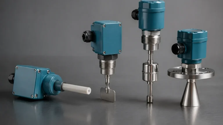
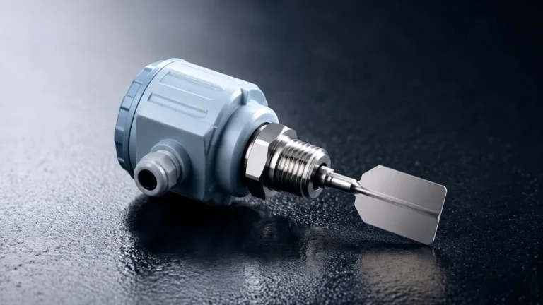
* Vibrating (Tuning Fork): The sensor vibrates at a specific frequency; when immersed in liquid, the frequency shifts, triggering the switch.
* Optical: Uses infrared light refraction to detect the presence of liquid.
In a 4-lead configuration, these principles are often doubled or paired with specific diagnostic leads to enhance the information sent to the Programmable Logic Controller (PLC) or Distributed Control System (DCS).
Understanding the 4 Lead Switch Configuration
The term "4 lead" refers to the number of electrical conductors exiting the sensor housing. In the context of industrial level switches, this typically indicates one of three functional setups:
1. Dual-Point Switching
This is the most frequent application for a 4 lead switch. The device contains two independent switches within a single stem or housing. For example, one switch might be positioned at the "High" level and the other at the "Low" level. Each switch has two dedicated leads (2 leads x 2 switches = 4 leads). This allows a single process entry point to manage both pump-start and pump-stop functions.
2. DPDT (Double Pole Double Throw) Logic
A 4-lead configuration can also represent a simplified DPDT or a dual-circuit SPST (Single Pole Single Throw) setup. This provides redundancy; if one circuit fails, the second circuit provides a backup signal. It is also used when one set of leads triggers a local alarm (like a siren or strobe) while the second set sends a signal to the control room.
3. Active 4-Wire Sensors
In more advanced electronic level switches (like ultrasonic or capacitance switches), 4 leads are used to separate the power supply from the signal output. Two leads provide the DC or AC power required to run the internal electronics, while the remaining two leads provide the dry contact or transistor output. This is distinct from "loop-powered" 2-wire sensors.
Technical Comparison: Switch Types
When selecting a 4 lead switch, the technology must match the media and the environmental conditions. The following table outlines common options for B2B industrial applications.
| Switch Type | Common Application | Lead Configuration | Advantages | Limitations |
| :— | :— | :— | :— | :— |
| Magnetic Float | Water tanks, oil sumps | 2x SPST (4 leads) | Simple, no power required for contacts | Susceptible to coating/debris |
| Vibrating Fork | Chemical processing | Power (2) + Output (2) | High reliability, ignores foam | Higher initial cost |
| Conductive | Wastewater, acids | High (2) + Low (2) | No moving parts | Requires conductive liquid |
| Optical | Clean pharmaceutical | Power (2) + Output (2) | Very small footprint | Not for opaque or coating liquids |
Selection Criteria for Industrial Applications
Choosing the correct 4 lead switch requires an evaluation of both the electrical requirements and the physical process parameters.
Media Compatibility
The material of the wetted parts must be chemically compatible with the liquid. Stainless steel (316L) is the standard for most industrial applications, but aggressive chemicals may require PVC, PP, or PTFE (Teflon) coatings. For the 4-lead wiring itself, ensure the insulation material (e.g., XLPE or PVC) can withstand the ambient temperature near the tank.
Pressure and Temperature
Standard float switches are often rated for pressures up to 30 bar (approx. 435 PSI) and temperatures up to 120°C (248°F). If your application involves high-pressure steam or cryogenic liquids, specialized 4 lead switches with heavy-duty housings and high-temperature wiring are required.
Electrical Load
It is a common mistake to wire a level switch directly to a high-draw motor. Most 4 lead switches, especially those using reed technology, are designed for signal levels (e.g., 20VA to 50VA). If you need to switch a pump directly, the 4 leads should be connected to an intermediate relay or a motor starter.
Installation and Wiring Considerations
Proper installation is critical to prevent premature failure and ensure accurate switching. When working with a 4 lead switch, follow these engineering best practices:
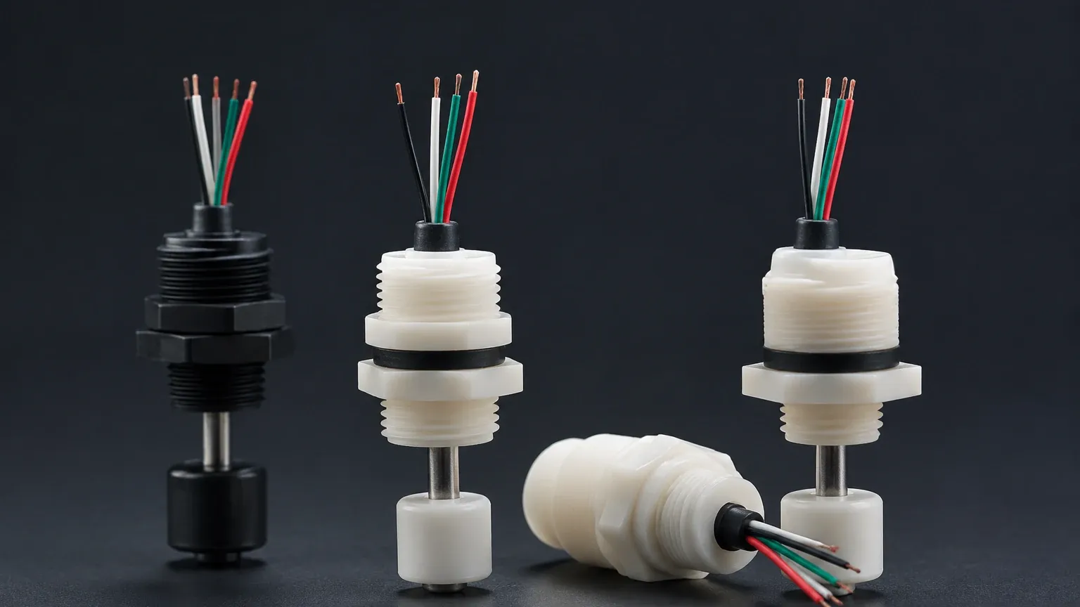
1. Lead Identification: Ensure you have the manufacturer’s wiring diagram. In a dual-float 4 lead switch, the leads are usually color-coded (e.g., Blue/Blue for Switch 1 and Black/Black for Switch 2). Mixing these up can result in the PLC receiving a "High" signal when the tank is actually "Low."
2. Conduit Sealing: For outdoor or wash-down environments, use liquid-tight conduit and ensure the cable entry is sealed. Moisture wicking down the leads is a primary cause of short circuits in 4-lead systems.
3. Vertical Alignment: Float-based switches must be installed within 30° of vertical. Excessive tilting can cause the float to bind on the stem, preventing the internal magnets from reaching the reed switches.
4. Turbulence Protection: In tanks with high agitation or inflow, the float can bounce, causing "chatter" in the 4-lead signal. Installing a stilling well (a pipe surrounding the switch) can stabilize the float.
Limitations and Common Risks
While the 4 lead switch is a versatile tool, it has specific limitations that engineers must account for during the design phase:
* Contact Welding: If the electrical surge (inrush current) exceeds the switch rating, the internal contacts can weld shut. Always use surge suppression (like a flyback diode for DC or a varistor for AC) when switching inductive loads.
* Mechanical Wear: Any switch with moving parts (like a float) has a finite cycle life. In applications with constant cycling, solid-state switches with 4-lead power/signal configurations are often preferred.
* Build-up: In wastewater or viscous food products, material can build up on the stem or fork. This can "pin" the switch in one position, leading to false readings or tank overflows.
Frequently Asked Questions (FAQ)
Q: Can I use a 4 lead switch as a 2-wire switch?
A: Yes. If the switch provides two independent circuits, you can simply use one pair of leads and insulate the unused pair. However, ensure the unused leads are capped to prevent accidental grounding.
Q: What is the benefit of a 4-lead configuration over a 3-lead (SPDT) configuration?
A: A 3-lead SPDT switch has one common wire. A 4-lead switch (typically 2x SPST) provides complete electrical isolation between the two circuits. This is vital if the two signals are going to different systems (e.g., one to a 24VDC PLC and one to a 110VAC alarm panel).
Q: How do I test a 4 lead switch during maintenance?
A: Use a multimeter set to continuity (ohms). Manually move the float or immerse the sensor and check that each pair of leads opens and closes according to the specification. There should be infinite resistance between the two separate circuits.
Q: Are 4 lead switches suitable for hazardous areas?
A: Yes, but they must be rated as "Intrinsically Safe" or "Explosion Proof." Because a 4 lead switch is a simple apparatus in many cases, it can be used with an intrinsic safety barrier to limit the energy available for ignition.
Conclusion
The 4 lead switch is a fundamental component for B2B process control, offering a balance of simplicity and multi-functional capability. By providing two independent signals or separating power from logic, these devices allow for sophisticated tank management and safety interlocking. When selecting a switch, engineers must prioritize media compatibility, electrical ratings, and environmental protection to ensure long-term performance.
For those designing new systems or replacing legacy hardware, it is advisable to consult detailed product specifications to ensure the chosen wiring configuration aligns with the control architecture. Reliable point-level detection is the first line of defense against process failures, making the humble 4 lead switch a critical asset in any industrial facility.