V-guard Switches Review
V-guard Switches Review
In the landscape of industrial automation and process safety, the selection of reliable point-level detection components is a critical engineering decision. This V-guard switches review examines the technical specifications, operational principles, and application suitability of these devices within B2B industrial environments. Level switches serve as the primary line of defense against tank overfills, dry-run conditions in pumps, and precise inventory management in silos. Understanding how these instruments interface with modern control systems is essential for maintaining plant safety and operational efficiency.
Measurement Principles of Industrial Level Switches
Before evaluating specific models like those in the V-guard range, it is necessary to understand the physics governing point-level detection. Industrial Level Switches utilize various physical properties of the media to trigger a state change in the electrical output.
Buoyancy (Float) Principle
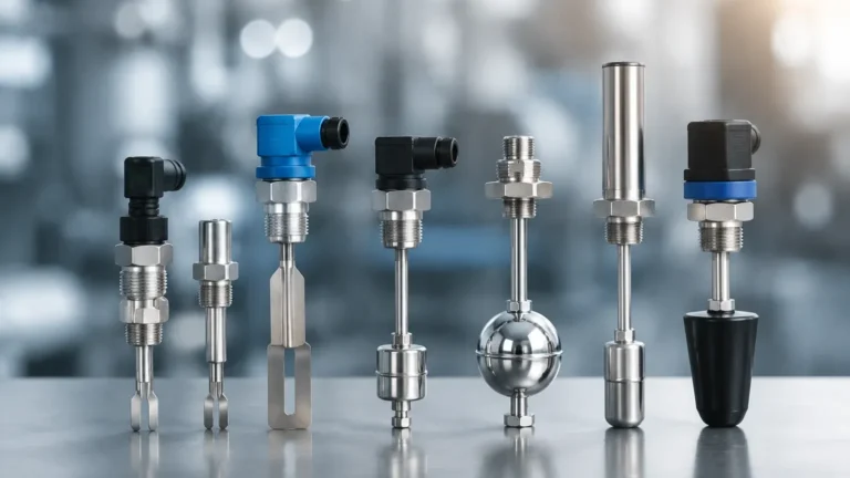
Float-based switches are among the most established technologies. They rely on a float containing a permanent magnet that moves with the liquid level. As the float reaches a predetermined point, the magnetic field actuates a reed switch or a microswitch. This method is highly reliable for clean, non-coating liquids where density is relatively constant.
Vibrating Tuning Fork Principle
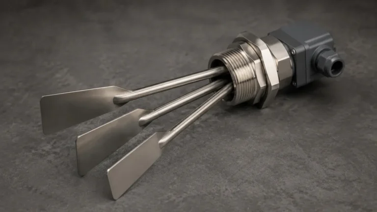
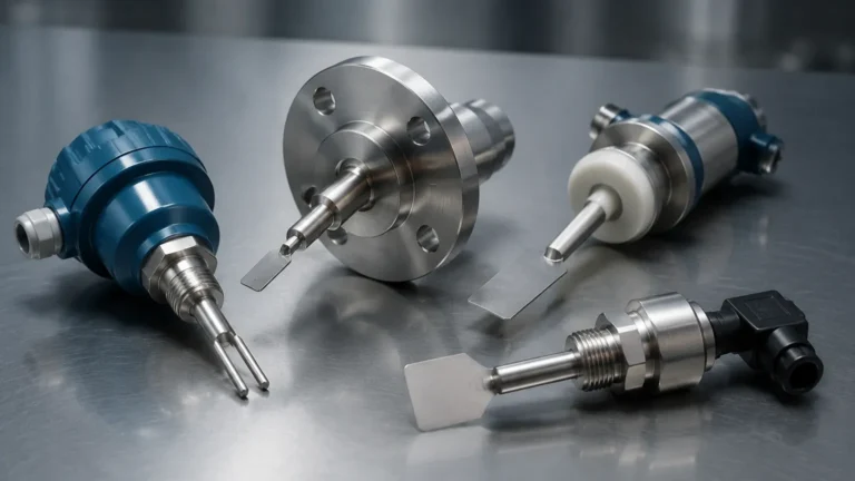
The vibrating level switch uses piezoelectric crystals to energize a tuning fork at its natural resonant frequency. When the fork is immersed in a medium (liquid or solid), the frequency changes or the vibration is damped. The electronics detect this shift and convert it into a switching signal. This principle is particularly effective for detecting powders, granules, and liquids with varying viscosity.
Capacitance Principle
Capacitive level switches measure the change in capacitance between a probe and the vessel wall (or a reference probe). As the media displaces air, the dielectric constant changes, altering the measured capacitance. This technology is versatile but requires calibration based on the specific dielectric properties of the material being measured.
Conductivity Principle
Used exclusively for conductive liquids, these switches utilize a low-voltage electrode. When the liquid touches the electrode, a circuit is completed through the media to the tank wall or a ground probe. This is a cost-effective solution for water-based applications but is unsuitable for oils or hydrocarbons.
Technical Review: V-guard Switches in Industrial Context
When conducting a V-guard switches review for industrial applications, engineers must look beyond basic switching and evaluate the robust construction required for 24/7 operations. V-guard components are frequently utilized in power management and auxiliary control circuits, but their application in level sensing requires specific scrutiny regarding environmental sealing and electrical endurance.
Build Quality and Material Compatibility
Most industrial-grade switches in this category feature housings rated at IP65 or IP67, ensuring protection against dust ingress and moisture. For chemical processing, the wetted parts—the components in direct contact with the media—must be selected carefully. Common materials include 304 or 316L stainless steel, PP (Polypropylene), or PTFE (Teflon) for corrosive environments.
Electrical Performance and Integration
A key aspect of this review is the electrical interface. Industrial level switches typically offer SPDT (Single Pole Double Throw) or DPDT (Double Pole Double Throw) relay outputs. In modern PLC-driven environments, PNP/NPN transistor outputs are also common due to their high switching frequency and lack of mechanical wear. V-guard's focus on voltage stability and surge protection in their broader product line translates well to the reliability of their switching logic under fluctuating industrial power conditions.
Response Time and Sensitivity
In high-speed filling lines or volatile chemical reactions, response time is measured in milliseconds. Vibrating forks generally offer the fastest response, while float switches may have a slight lag due to mechanical inertia. The V-guard switches reviewed demonstrate consistent repeatability, which is the ability of the switch to trigger at the exact same level every time, a vital metric for process consistency.
Selection Criteria for Level Switches
Choosing the correct switch involves matching the technology to the physical properties of the media and the constraints of the vessel. The following table provides a generalized selection guide based on common industrial parameters.
Table 1: Industrial Level Switch Selection Guide
| Media Type | Recommended Technology | Temperature Range (°C) | Max Pressure (bar) | Key Advantage |
| :— | :— | :— | :— | :— |
| Clean Water | Float / Conductivity | -20 to +100 | 10 – 20 | Low cost, simple setup |
| Corrosive Acids | PTFE-coated Capacitance | -40 to +150 | 40 | Chemical resistance |
| Viscous Oils | Vibrating Tuning Fork | -50 to +200 | 64 | Ignores coating/buildup |
| Fine Powders | Vibrating Rod / Fork | -40 to +80 | Atmospheric | High sensitivity |
| Wastewater | Ultrasonic (Point) | -20 to +70 | 3 | Non-contact detection |
Installation Considerations and Best Practices
Proper installation is as critical as the selection of the instrument itself. Failure to account for vessel geometry or internal obstructions can lead to false triggers or mechanical damage.
1. Avoid Turbulence: Switches should not be installed directly in the path of an inlet flow. The kinetic energy of the incoming fluid can cause mechanical fatigue in float arms or cause "chatter" in the switching relay. If placement near an inlet is unavoidable, a stilling well or baffle should be installed.
2. Orientation: While tuning forks can often be mounted in any orientation, they should be positioned so that material can easily drain off the forks. For horizontal mounting in solids, the forks should be oriented vertically (side-by-side) so that material does not bridge between the tines.
3. No-Go Zones: Ensure the switch is not placed near agitators or internal heating coils. For capacitive switches, maintain a minimum distance from the vessel wall to prevent interference with the electromagnetic field.
4. Cable Entry: Always point cable glands downward to prevent moisture from traveling along the cable and into the housing. Use drip loops in all wiring configurations.

Limitations and Operational Risks
No single level switch technology is universal. Engineers must be aware of the following limitations identified during the V-guard switches review process:
* Coating and Scaling: In applications involving lime slurry or heavy resins, material can build up on the sensor. While tuning forks are somewhat resistant to this, float switches and capacitive probes may fail if the coating becomes too thick or conductive.
* Turbulence and Foam: Mechanical switches can be confused by surface foam, treating it as a solid liquid level. In these cases, ultrasonic or specialized tuning forks with adjustable sensitivity are required.
* Pressure and Temperature Extremes: Standard switches often have limits around 150°C and 40 bar. High-pressure boilers or cryogenic storage require specialized hermetically sealed units with extended cooling necks for the electronics.
Frequently Asked Questions (FAQ)
Q: Can a level switch be used for continuous level measurement?
A: No. A level switch is a point-detection device that provides a discrete "on/off" signal. For continuous monitoring (0-100%), you would require a radar level meter or a hydrostatic transmitter.
Q: What is the difference between N/O and N/C contacts?
A: N/O (Normally Open) means the circuit is open when the switch is not actuated. N/C (Normally Closed) means the circuit is closed. For safety-critical applications like high-level alarms, N/C is often preferred because a wire break will trigger the same alarm state as a high level (fail-safe).
Q: How do I handle switching for highly flammable liquids?
A: You must use intrinsically safe (IS) switches or explosion-proof (Ex d) enclosures. These devices are designed to limit electrical energy so that a spark cannot ignite the surrounding atmosphere.
Q: Is it possible to test a level switch without filling the tank?
A: Yes, many modern vibrating and electronic switches include a "test" button or a magnetic test point that simulates a covered state to verify the logic loop and alarm sirens.
Conclusion
The V-guard switches review highlights the importance of matching electrical reliability with mechanical robustness. Whether utilizing float, vibration, or capacitive principles, the goal remains the same: providing a definitive signal to prevent process excursions. By following the selection criteria and installation guidelines outlined above, plant engineers can ensure that their level control systems provide long-term accuracy and safety. For those seeking a wider range of industrial-grade solutions, exploring various Level Switches tailored to specific chemical and physical environments is the next logical step in system design.