Xp Switches
Xp Switches
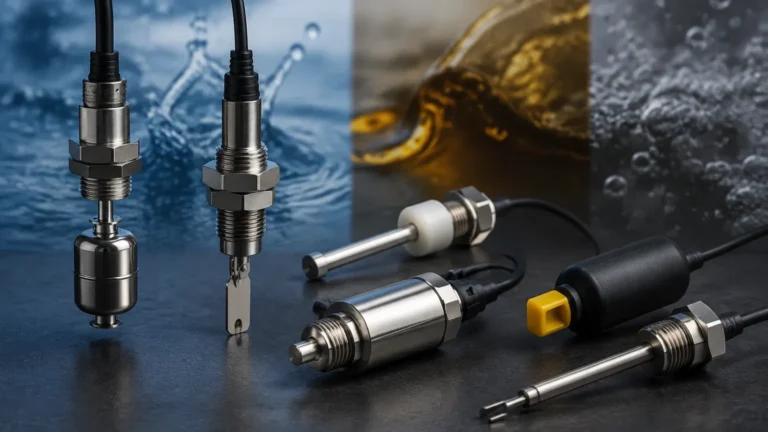
In industrial environments where flammable gases, vapors, or combustible dusts are present, standard electrical components represent a significant ignition risk. Explosion-proof switches, commonly referred to as xp switches, are specialized point-level detection devices engineered to contain any internal explosion and prevent the ignition of the surrounding hazardous atmosphere. For process engineers and safety officers, selecting the correct Level Switches is not merely a matter of operational efficiency but a critical component of plant safety and regulatory compliance.
Welk provides a range of level measurement solutions designed to meet these rigorous safety standards. This guide examines the technical principles, selection criteria, and installation requirements for xp switches used in hazardous area classifications.
Understanding Explosion-Proof (XP) Level Switches
The term "explosion-proof" does not imply that the switch can withstand an external explosion. Instead, it refers to the construction of the switch housing. An XP enclosure is designed to contain an internal explosion of a specified gas or vapor. If an internal spark ignites flammable material that has migrated into the housing, the enclosure must be strong enough to withstand the pressure without rupturing and must cool the escaping combustion gases through flame paths (such as threaded joints or machined flanges) so that they do not ignite the external atmosphere.
In the context of level measurement, xp switches are categorized by their protection methods, typically falling under NEMA 7 (hazardous gas) or NEMA 9 (hazardous dust) in North America, or under ATEX/IECEx "Ex d" (flameproof) or "Ex i" (intrinsically safe) standards internationally.
Core Measurement Principles for Hazardous Environments
Before selecting a specific model, it is essential to understand the underlying physics of different level detection technologies. Each principle offers distinct advantages depending on the media being measured.
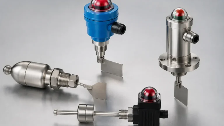
1. Vibrating Fork (Tuning Fork)
This technology utilizes a piezoelectric crystal to vibrate a metal fork at its natural resonance frequency (typically between 800 Hz and 1,200 Hz). When the fork is immersed in a liquid or solid, the frequency changes. The electronics detect this shift and trigger the switch output.
* XP Advantage: These are solid-state devices with no moving parts to wear out, making them highly reliable in volatile chemical tanks.
2. Magnetic Float Switches
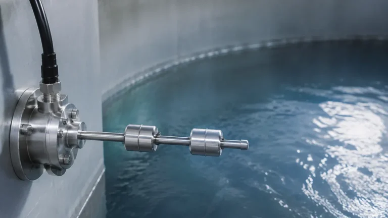
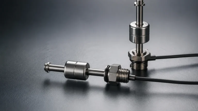
Magnetic float switches rely on a float containing a permanent magnet that moves up and down a stem. Inside the stem, a hermetically sealed reed switch is actuated by the magnet's proximity.
* XP Advantage: The electrical contact is completely isolated from the process media within a sealed stem, providing an inherent layer of protection that is further bolstered by an explosion-proof junction box.
3. Capacitance Level Switches
Capacitance switches measure the change in electrical capacitance between a probe and the tank wall (or a reference probe). As the level rises, the air surrounding the probe is replaced by the process material, which has a different dielectric constant ($ε$).
* XP Advantage: Suitable for high-temperature and high-pressure applications where mechanical switches might fail.
4. Rotary Paddle Switches
Commonly used for dry bulk solids, a motor slowly rotates a paddle. When material reaches the paddle, it creates torque that trips a microswitch and stops the motor.
* XP Advantage: Essential for silos containing combustible dusts (e.g., grain, sugar, or plastic powders) where NEMA 9 or ATEX Dust ratings are required.
Technical Selection Criteria for XP Switches
Selecting the appropriate xp switches requires a detailed analysis of the application's physical and chemical properties. Engineers should evaluate the following parameters:
Media Characteristics
* Density: For float-based switches, the media must have a specific gravity higher than the float's buoyancy limit. Typically, a minimum density of 0.5 g/cm³ (500 kg/m³) is required for standard floats.
* Viscosity: High-viscosity or "sticky" liquids can cause mechanical floats or paddles to bind. Vibrating forks are generally more resistant to coating, though extreme buildup can still cause false positives.
* Dielectric Constant: For capacitance switches, a minimum difference between the dielectric of the air and the media is necessary (usually $ε > 1.5$).
Process Conditions
* Temperature: Standard XP housings are often rated for -40°C to +80°C (-40°F to +176°F). For cryogenic or high-heat applications (up to 250°C), thermal extensions or remote electronics are required to protect the XP-rated housing from heat conduction.
* Pressure: The wetted parts must be rated for the maximum vessel pressure. Stainless steel (316L) is the standard for high-pressure xp switches, often rated up to 40 bar (580 psi) or higher.
Hazardous Area Classification
It is vital to match the switch to the specific zone or division of the site:
* Class I, Div 1 / Zone 0 or 1: Areas where ignitable concentrations of flammable gases are present under normal operating conditions.
* Class II, Div 1 / Zone 20 or 21: Areas where combustible dust is present.
* Gas Groups: Ensure the device is rated for the specific gas present (e.g., Group B for Hydrogen, Group D for Methane).
Comparison of XP Level Switch Technologies
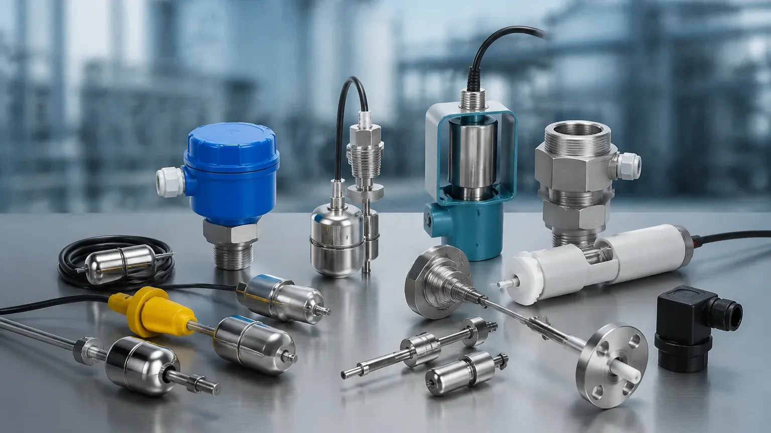
| Technology | Media Type | Primary Benefit | Limitation | Typical XP Rating |
| :— | :— | :— | :— | :— |
| Vibrating Fork | Liquids/Powders | No moving parts; ignores foam | High viscosity may cause damping | ATEX Ex d / Ex ia |
| Float Switch | Clean Liquids | Simple; no power required for reed type | Susceptible to scaling/fouling | NEMA 7/9, Class I Div 1 |
| Capacitance | Liquids/Solids | High temp/pressure resistance | Requires calibration for different media | ATEX Ex d |
| Rotary Paddle | Dry Solids | Robust for heavy materials | Mechanical wear on motor/seals | NEMA 9 (Dust Ignition Proof) |
Installation and Maintenance in Classified Areas
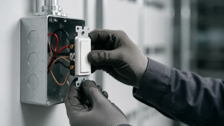
The integrity of an explosion-proof system depends entirely on proper installation. Even the highest quality xp switches will fail to provide safety if the installation bypasses XP protocols.
Conduit Sealing
In XP installations, conduit runs must be sealed using certified sealing fittings (such as EYS or EZS types). These fittings are filled with a sealing compound that prevents the passage of gases, vapors, or flames from one portion of the electrical installation to another through the conduit. The seal must be placed within 450 mm (18 inches) of the switch enclosure.
Thread Engagement and Grounding
For an enclosure to remain flameproof, all threaded entries must have a minimum of five full threads engaged. This ensures that the flame path is long enough to cool any escaping gases. Furthermore, proper grounding (both internal and external) is mandatory to prevent static discharge, which is a common ignition source in hazardous areas.
Maintenance Checklist
1. Inspect Flame Paths: Ensure machined surfaces of the housing cover are free of scratches, corrosion, or paint. Never use a gasket on a flameproof joint unless specifically designed by the manufacturer.
2. Verify Torque: Ensure all bolts securing the XP cover are tightened to the manufacturer's specified torque.
3. Check Seals: Inspect conduit seals for cracks or degradation over time.
Limitations and Critical Safety Considerations
While xp switches are robust, they are not universal solutions. Engineers must be aware of the following boundaries:
* Intrusive Nature: Most XP switches are intrusive, meaning they require a process connection (threaded or flanged). This introduces a potential leak point. For extremely toxic or high-pressure media, non-contacting methods like ultrasonic or radar may be preferred, though these also require XP-rated transmitters.
* Coating and Buildup: In applications with heavy crystallization or viscous buildup, mechanical and vibrating switches may provide false "high" signals. Regular cleaning or the use of "active shield" capacitance probes may be necessary.
* Power Requirements: Unlike simple mechanical switches, vibrating forks and rotary paddles require a power supply (typically 24V DC or 110/230V AC). In hazardous areas, this power must be delivered via XP-rated cabling or through an intrinsically safe barrier if the device is rated "Ex ia".
Frequently Asked Questions
Q: Can I use a standard level switch in a hazardous area if I put it in an XP box?
A: No. The entire assembly, including the sensor probe and the electronics, must be certified as a system. A standard sensor might produce a spark at the process connection which the external box cannot contain.
Q: What is the difference between "Explosion-Proof" and "Intrinsically Safe"?
A: Explosion-proof (XP) relies on a heavy-duty enclosure to contain an explosion. Intrinsically Safe (IS) limits the electrical energy available in the circuit so that a spark or thermal effect cannot occur with enough energy to cause ignition. IS systems require the use of an isolation barrier in the safe area.
Q: How do I choose between a vibrating fork and a float switch for an XP application?
A: Choose a vibrating fork if the liquid is turbulent, contains bubbles, or if you want a device with no moving parts. Choose a float switch for simple, low-power applications with clean, non-coating liquids where cost-effectiveness is a priority.
Q: Do xp switches require periodic recalibration?
A: Mechanical float switches and vibrating forks typically do not require calibration. Capacitance-based xp switches may require recalibration if the dielectric constant of the process media changes significantly.
For more detailed technical specifications and to explore specific models for your application, you can Review product options and application support to ensure your facility remains compliant and safe.