4 Way Switches Explained
4 Way Switches Explained
In the realm of industrial automation and process control, the term "4-way switch" often leads to a cross-disciplinary conversation. While residential electricians may associate the term with controlling a single light fixture from three or more locations, engineers and plant operators in the process industries view 4-way configurations through the lens of multi-point level detection. In this context, 4 way switches explained refers to the integration of four distinct switching points within a single vessel or tank to manage complex pump logic, overflow prevention, and dry-run protection.
Accurate level detection is critical for maintaining safety and efficiency in water treatment, chemical processing, and oil and gas applications. Utilizing Level Switches with four independent setpoints allows for a sophisticated level of control that single-point or dual-point switches cannot provide. This guide provides a technical deep dive into the principles, selection, and application of 4-point industrial level switches.
Measurement Principles of Multi-Point Level Switches
Before selecting a 4-way level switch configuration, it is essential to understand the underlying physical principles used to detect the presence or absence of a medium at specific heights. Industrial level switches typically employ one of the following four technologies to achieve multi-point detection.
1. Magnetic Float Technology
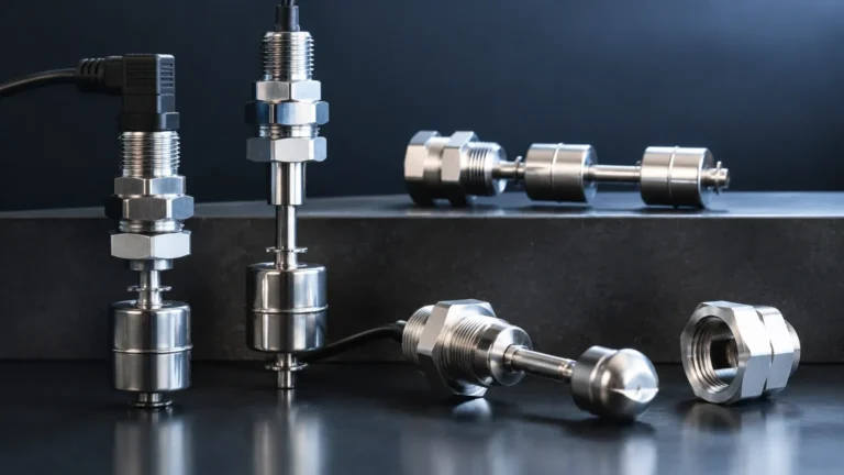
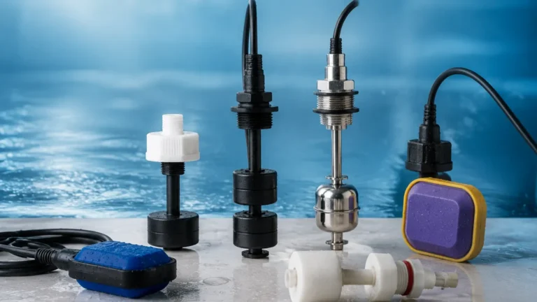
Magnetic float switches are the most common solution for 4-point detection in clean liquids. The system consists of a hollow stem containing four stationary reed switches positioned at specific heights. A float containing a permanent magnet slides up and down the stem as the liquid level changes. When the magnet reaches the level of a reed switch, the magnetic field causes the switch contacts to open or close.
* Advantages: Simple, reliable, and requires no external power to operate the reed contacts.
* Limitations: Susceptible to fouling if the liquid contains debris or is highly viscous.
2. Conductive Level Detection
For conductive liquids (such as water, acids, or caustic solutions), conductivity probes are a cost-effective 4-way solution. This setup involves four electrodes (plus one reference electrode) of varying lengths. When the conductive liquid touches an electrode, a low-voltage circuit is completed between that electrode and the reference probe (or the tank wall), triggering a relay.
* Advantages: No moving parts, highly durable in corrosive environments.
* Limitations: Only works with conductive liquids; prone to false triggers if there is significant foam or buildup.
* 4 way switches explained in this context: Each electrode length represents one "way" or "point" of detection.
3. Ultrasonic Gap Switches
Ultrasonic gap switches use a pair of piezoelectric crystals separated by a small gap. When the gap is filled with liquid, ultrasonic waves travel across; when the gap is filled with air or gas, the signal is attenuated. To achieve a 4-way configuration, four separate sensor heads are typically mounted on a single flange or bracket at different depths.
* Advantages: Highly accurate, unaffected by changes in density or conductivity.
* Limitations: Higher cost per point compared to float or conductive types.
4. Tuning Fork (Vibrating) Switches
Tuning fork switches vibrate at a specific frequency in air. When submerged in liquid, the frequency shifts, which is detected by the electronics. While these are usually single-point devices, they are frequently manifolded together to create a 4-point safety and control array in critical chemical applications.
Typical 4-Point Level Configuration and Logic
When we look at 4 way switches explained from a control logic perspective, the four points are almost always assigned to specific safety and operational functions. A standard configuration in an industrial tank often follows this hierarchy:
1. High-High (HH) Alarm: This is the ultimate safety limit. If the liquid reaches this point, the switch triggers an emergency shutdown (ESD) of all inlet pumps and may activate an audible alarm to prevent a catastrophic overflow.
2. High (H) Level / Pump Stop: This point is used for routine process control. In a filling application, reaching this switch signals the PLC (Programmable Logic Controller) to stop the fill pump.
3. Low (L) Level / Pump Start: This point initiates the filling process. When the level drops below this switch, the PLC activates the inlet pump to replenish the tank.
4. Low-Low (LL) Alarm: This is a dry-run protection point. If the level falls to this switch, it indicates a failure in the supply system. The switch triggers a shutdown of outlet pumps to prevent cavitation and mechanical damage.
Selection Criteria for 4-Way Level Switches
Choosing the right 4-point level switch requires a detailed analysis of the process media and the vessel environment. The following table provides a comparison of the most common technologies used for 4-way industrial level detection.
| Feature | Magnetic Float | Conductive Probes | Ultrasonic Gap | Tuning Fork Array |
| :— | :— | :— | :— | :— |
| Media Type | Clean liquids | Conductive liquids | Most liquids | Liquids & Slurries |
| Moving Parts | Yes | No | No | No (Vibrating) |
| Max Temperature | Up to 200°C | Up to 150°C | Up to 150°C | Up to 250°C |
| Max Pressure | Up to 40 bar | Up to 20 bar | Up to 60 bar | Up to 100 bar |
| Maintenance | Moderate | Low | Low | Low |
| Cost | Economical | Lowest | High | High |
Material Compatibility
In chemical applications, the wetted parts of the switch must be compatible with the medium. 316 Stainless Steel is the standard, but for highly corrosive acids, materials like PTFE (Teflon), PP (Polypropylene), or PVDF are required. When considering 4 way switches explained for corrosive environments, ensure that the stem, floats, or electrodes are fully encapsulated in resistant plastics.
Viscosity and Solids
If the liquid has a high viscosity (e.g., heavy oils) or contains suspended solids (e.g., wastewater), magnetic floats may stick. In these cases, non-contact ultrasonic arrays or vibrating tuning forks are preferred as they are less likely to be affected by buildup.
Installation and Engineering Considerations
Proper installation is paramount to ensuring the long-term reliability of a 4-way level switch system. Engineers should adhere to the following guidelines:
* Mounting Position: Multi-point switches are typically top-mounted. Ensure there is enough overhead clearance to install a probe that may be 2 meters (approx. 6.5 feet) or longer.
* Still Wells: In tanks with heavy agitation or turbulence, a still well (a pipe surrounding the switch) should be installed. This prevents the float or electrodes from being damaged by lateral forces and stabilizes the liquid surface for more accurate switching.
* Dead Zones: Be aware of the "dead zone" at the top and bottom of the probe. For magnetic float switches, the highest switch point (HH) usually cannot be closer than 50 mm (approx. 2 inches) to the mounting flange due to the physical dimensions of the float and the internal wiring.
* Wiring and Termination: A 4-way switch will have multiple wires (often 5 or 8 wires depending on whether they share a common ground). Using a junction box with clear labeling is essential for troubleshooting. For hazardous areas, ensure the switch is wired through an intrinsically safe (IS) barrier.
Common Risks and Limitations
While 4-way level switches are highly efficient, they are not without limitations. Understanding these risks is part of having 4 way switches explained comprehensively.
1. Turbulence and Foam: As mentioned, turbulence can cause "chatter" in float switches, where the switch rapidly opens and closes. This can burn out relay contacts or confuse the PLC. Foam can also cause false high-level readings in conductive and ultrasonic switches.
2. Coating and Buildup: In conductive switches, a film of conductive liquid coating the insulation between electrodes can create a "bridge," causing the switch to stay "on" even after the level has dropped.
3. Single Point of Failure: Because all four switch points are often housed in a single probe or stem, physical damage to the stem (e.g., from a falling object or extreme surge) can disable all four points of detection simultaneously. For high-SIL (Safety Integrity Level) applications, it is often recommended to use redundant, independent switches.
Frequently Asked Questions (FAQs)
Q: Can I adjust the switch points after installation?
A: For most magnetic float and conductive probe switches, the points are fixed at the factory based on the lengths specified during ordering. However, some conductive probes allow the user to cut the electrodes to the desired length on-site. Always confirm adjustability with the manufacturer before purchase.
Q: What is the difference between SPST and SPDT contacts in these switches?
A: SPST (Single Pole Single Throw) contacts are either open or closed. SPDT (Single Pole Double Throw) contacts provide both a normally open (NO) and normally closed (NC) option, offering more flexibility for fail-safe wiring.
Q: How do I test a 4-way switch without filling the tank?
A: For float switches, you can manually slide the float along the stem if the unit is removed from the tank. For conductive and ultrasonic types, you can submerge the sensor head or electrodes in a small container of the process liquid to verify the relay logic.
Conclusion
Having 4 way switches explained in an industrial context reveals a versatile and essential tool for process management. By integrating four distinct detection points into a single instrument, facilities can achieve complex control over pumps and alarms while minimizing the number of tank penetrations. Whether utilizing magnetic floats for clean water or conductive probes for chemical processing, selecting the right technology and following strict installation protocols ensures a reliable and safe operation.
For those seeking specific hardware solutions, reviewing various Level Switches options will help identify the specific model that meets the pressure, temperature, and chemical compatibility requirements of your project. Confirming the exact distances for HH, H, L, and LL points during the design phase is the final step toward a successful multi-point level control implementation.