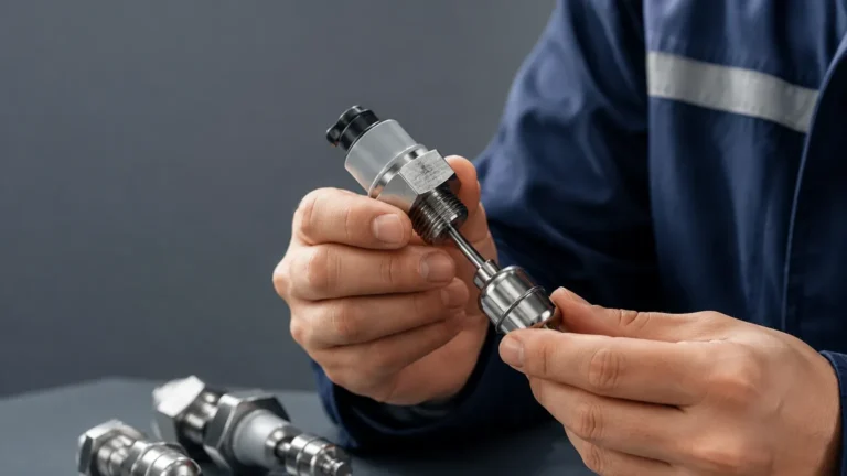
Level Sensor 0 10v
Level Sensor 0 10v
In industrial automation and process control, the level sensor 0 10v represents one of the most established standards for analog signal transmission. Utilizing a voltage-based output, these sensors provide continuous monitoring of liquid or solid levels, translating physical height into a proportional electrical signal. While modern industry often debates the merits of voltage versus current loops, the 0-10V interface remains a staple in building management systems (BMS), localized PLC (Programmable Logic Controller) environments, and laboratory equipment due to its simplicity and compatibility with high-impedance inputs.
Selecting the correct level sensor 0 10v requires an understanding of both the sensing technology (how the level is measured) and the signal characteristics (how the data is transmitted). This guide examines the technical principles, application suitability, and installation requirements for these instruments within professional engineering contexts.
Measurement Principles for 0-10V Level Sensors
A level sensor 0 10v is not a single type of device but rather a category of instruments equipped with a specific output stage. The underlying measurement technology varies based on the medium and the environment.
Ultrasonic Level Measurement
Ultrasonic sensors are non-contact devices that emit high-frequency sound pulses. These pulses reflect off the surface of the material and return to the transducer. The sensor calculates the distance based on the time-of-flight. The internal electronics then scale this distance to a 0-10V signal. For example, in a 5-meter (16.4 ft) tank, 0V might represent an empty state (5m distance), while 10V represents a full state (0.5m distance from the sensor).
Hydrostatic Pressure Measurement
Hydrostatic sensors are submersible or externally mounted pressure transmitters. They measure the head pressure exerted by the liquid column above the sensor diaphragm. Since pressure is directly proportional to the height of the liquid (based on the density of the fluid), the sensor converts this mechanical force into a 10V maximum signal at full scale. These are preferred for deep wells, reservoirs, and vented tanks where foam or surface turbulence might interfere with ultrasonic signals.
Radar (ToF) Level Measurement
Similar to ultrasonic sensors but using electromagnetic waves, radar level meters offer higher precision and are unaffected by air temperature, vacuum, or high pressure. The 0-10V output variant is frequently used in specialized machinery where high-speed processing of the level data is required without the conversion overhead of digital protocols.
Technical Comparison: 0-10V vs. Alternative Signals
When specifying a level sensor 0 10v, engineers must consider why a voltage signal is chosen over the more common 4-20mA current loop.
| Feature | 0-10V Analog Signal | 4-20mA Current Loop |
| :— | :— | :— |
| Transmission Distance | Short (typically < 15m / 50ft) | Long (up to 1000m / 3280ft) |
| Noise Immunity | Susceptible to EMI/RFI | High resistance to noise |
| Power Consumption | Generally lower | Slightly higher |
| Fault Detection | Cannot distinguish 0V from a broken wire | 4mA offset allows for cable break detection |
| Input Impedance | Requires high impedance (10kΩ+) | Requires low impedance (250Ω typical) |
The level sensor 0 10v is ideal for localized control panels where the sensor and the controller share a common ground and are located in close proximity. It is particularly prevalent in HVAC systems and localized water treatment skids.
Integration with Level Switches for Redundancy
While a level sensor 0 10v provides continuous data, critical process safety often mandates the use of point-level detection. Continuous sensors can experience signal drift or electronic failure. To prevent catastrophic overflows or dry-run conditions in pumps, engineers integrate independent Level Switches into the system.
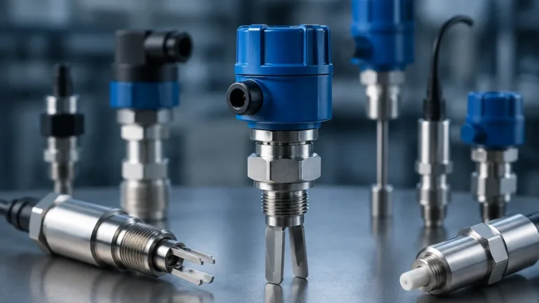
Level switches act as a secondary safety layer. For instance, if the 0-10V signal from an ultrasonic sensor fails to report a high-level condition due to foam interference, a mechanical float switch or a tuning fork level switch will provide a hard-wired digital signal to shut down the filling valve. This combination of continuous monitoring and discrete switching ensures both process efficiency and operational safety.
Selection Criteria for 0-10V Level Sensors
To ensure the longevity and accuracy of a level sensor 0 10v, several technical parameters must be evaluated during the procurement phase:
1. Measuring Range and Dead Zone: Every sensor has a maximum range (e.g., 10 meters) and a minimum distance it cannot measure (the dead zone). Ensure the 10V output corresponds to the actual maximum working height required.
2. Media Compatibility: For hydrostatic sensors, the housing material (316L stainless steel, PVC, or PTFE) must be compatible with the chemical properties of the fluid. For non-contact sensors, consider if the medium is prone to heavy vapor or dust.
3. Power Supply Requirements: Most 0-10V sensors require a stable 24V DC power supply. Unlike 2nd-wire 4-20mA sensors, 0-10V units typically require a 3-wire or 4-wire configuration (Power, Ground, and Signal).
4. Resolution and Accuracy: Check the bit-depth of the internal Digital-to-Analog Converter (DAC). A higher resolution ensures that the 0-10V steps are smooth enough for precise control loops.
Installation and Wiring Best Practices
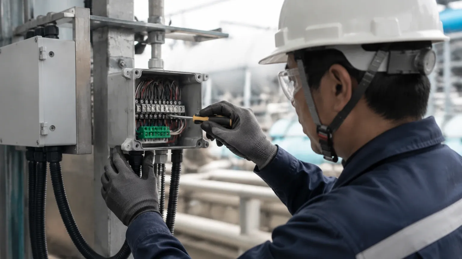
The performance of a level sensor 0 10v is heavily dependent on the quality of the installation. Because voltage signals are sensitive to voltage drops and electromagnetic interference, the following guidelines should be followed:
Shielding and Grounding
Always use shielded twisted-pair cabling. The shield should be grounded at only one end (usually the controller side) to prevent ground loops. Ground loops can introduce a DC offset, causing a 5V signal to be read as 5.2V, leading to significant measurement errors.
Cable Length Considerations
Voltage signals suffer from IR drop (Voltage = Current × Resistance). Even though the input impedance of a PLC is high, very long cable runs can lead to signal degradation. If the distance between the sensor and the controller exceeds 15-20 meters (approx. 50-65 feet), it is advisable to use a signal conditioner or switch to a 4-20mA transmitter.
Mounting Position
For ultrasonic and radar 0-10V sensors, the transducer must be mounted perpendicular to the liquid surface. Avoid mounting the sensor near the tank wall to prevent false echoes from internal structures like ladders or agitators. For hydrostatic sensors, ensure the sensor is not placed directly in the path of turbulent inflow, which can cause pressure spikes and erratic voltage readings.
Limitations of the 0-10V Standard
Despite its utility, the level sensor 0 10v has inherent limitations that engineers must manage:
* Zero-Point Ambiguity: In a 0-10V system, a reading of 0V could mean the tank is empty, or it could mean the sensor has lost power or the wire is cut. This is why some systems prefer a 1-5V or 2-10V scale, providing a "live zero" for fault diagnostics.
* Voltage Sensitivity: If the power supply to the sensor is not regulated, fluctuations in the supply voltage can sometimes reflect in the output signal, depending on the sensor's internal voltage regulation quality.
Summary Selection Table
| Application | Recommended Technology | Why? |
| :— | :— | :— |
| Clean Water Tanks | Ultrasonic | Cost-effective, non-contact, easy to calibrate to 0-10V. |
| Fuel/Oil Storage | Hydrostatic | Reliable in enclosed tanks, no moving parts to clog. |
| Corrosive Chemicals | PTFE-coated Radar | High resistance to vapors and chemical attack. |
| Small Process Vessels | Capacitance | High speed and suitable for small footprint areas. |
| Safety Overfill Protection | Level Switches | Provides a fail-safe discrete signal independent of the analog loop. |
Frequently Asked Questions (FAQ)
Q: Can I convert a 4-20mA sensor to a 0-10V output?
A: Yes, by placing a 500-ohm precision resistor across the input terminals of a controller, a 4-20mA signal is converted to a 2-10V signal. However, using a native level sensor 0 10v is often more precise as it eliminates the tolerance errors of external resistors.
Q: What happens if the 0-10V signal is noisy?
A: Noise usually manifests as rapid fluctuations in the level reading. This can often be mitigated by adding a low-pass filter in the PLC software or by using a physical signal isolator. Ensuring the signal wire is kept away from high-voltage AC power lines is the most effective preventative measure.
Q: Is a 0-10V sensor suitable for outdoor use?
A: Yes, provided the sensor has an appropriate IP rating (IP67 or IP68). However, be aware that long cable runs from outdoor tanks to indoor control rooms may require surge protection to protect the 0-10V input card from lightning-induced transients.
Q: How do I calibrate the 0V and 10V points?
A: Most modern sensors feature a teach-in button or a digital interface (like RS485 or a handheld programmer). You define the "Zero" point (usually the bottom of the tank) and the "Span" point (the maximum fill level). The sensor's internal processor then maps these points to 0V and 10V respectively.
By following these engineering principles and selection criteria, technical professionals can successfully implement level sensor 0 10v technology to achieve reliable, continuous level monitoring in a wide range of industrial applications.