Level Sensor 0 5v
Level Sensor 0 5v
In the landscape of industrial automation and process control, the level sensor 0 5v remains a fundamental component for continuous liquid level monitoring. This type of sensor provides an analog voltage output that is directly proportional to the level of the substance being measured. Unlike discrete switches that only indicate whether a level has reached a specific point, a 0-5V sensor allows operators and control systems to track the exact volume or height of a fluid in real-time.
As a professional manufacturer, Welk specializes in integrating these analog outputs into various sensing technologies, including hydrostatic, ultrasonic, and radar systems. Understanding the underlying measurement principles and the technical nuances of voltage-based signaling is essential for engineers selecting instrumentation for water treatment, chemical processing, or industrial tank management.
Measurement Principles for 0-5V Output
A level sensor 0 5v is not defined by its physical sensing method, but rather by its electronic interface. Several distinct technologies can be configured to produce this signal.
Hydrostatic Pressure Sensing
Hydrostatic level sensors operate on the principle that the pressure at the bottom of a liquid column is directly proportional to the height of the liquid above it. The formula used is $P = \rho \cdot g \cdot h$, where $P$ is pressure, $\rho$ (rho) is the liquid density, $g$ is gravity, and $h$ is the height.
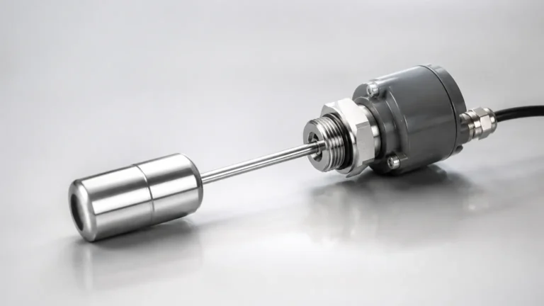
The sensor contains a sensing diaphragm—typically made of 316L stainless steel or ceramic—that deflects under pressure. This mechanical deflection is converted into an electrical signal by a piezo-resistive or capacitive element. The internal circuitry of the transmitter then scales this signal to a 0-5V DC range. For example, in a tank 5 meters (approx. 16.4 feet) deep, 0V would represent an empty tank (0 meters), while 5V would represent a full tank (5 meters).
Ultrasonic Time-of-Flight
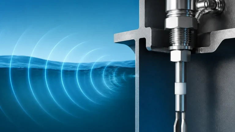
Ultrasonic sensors are non-contact devices that emit high-frequency sound waves from a transducer. These waves travel through the air, reflect off the surface of the liquid, and return to the sensor. By measuring the time-of-flight, the sensor calculates the distance to the liquid surface.
In a 0-5V configuration, the sensor's microprocessor maps the measured distance to the voltage output. This requires a calibration process where the "Empty" distance (maximum distance) is set to 0V and the "Full" distance (minimum distance) is set to 5V. These sensors are ideal for corrosive liquids where contact with the media must be avoided.
Radar (Microwave) Level Measurement
Similar to ultrasonic sensors, radar level meters use electromagnetic waves. Radar is particularly effective in environments with heavy vapor, dust, or temperature fluctuations that might affect the speed of sound. The high-frequency radar pulses are reflected by the dielectric constant of the liquid. The electronics then convert the reflected signal into a stable 0-5V output, providing high precision even in challenging process conditions.
Technical Integration: Why Choose 0-5V?
The choice of a 0-5V signal over the more common 4-20mA current loop often depends on the receiving hardware and the power constraints of the system.
1. Microcontroller Compatibility: Many small-scale automation controllers and IoT (Internet of Things) nodes have built-in Analog-to-Digital Converters (ADCs) that natively accept 0-5V or 0-3.3V. Using a 0-5V sensor eliminates the need for a precision resistor to convert current to voltage.
2. Power Consumption: Voltage-based sensors often consume less power than current-loop sensors, which must maintain at least 4mA at all times. This makes 0-5V sensors suitable for battery-powered or solar-powered remote monitoring stations.
3. Simplicity of Testing: A technician can verify the output of a level sensor 0 5v using a standard digital multimeter set to DC voltage without breaking the circuit, which simplifies field maintenance.
Selection Criteria for Industrial Applications
When selecting a level sensor 0 5v, engineers must evaluate the following parameters to ensure long-term reliability.
| Criteria | Description | Recommendation |
| :— | :— | :— |
| Media Compatibility | The chemical nature of the fluid (acidic, alkaline, oil). | Use PVDF for acids; 316L SS for water/oil. |
| Measurement Range | The total height of the tank or depth of the well. | Select a sensor with a range 10-20% higher than the maximum depth. |
| Temperature | The operating temperature of the liquid and ambient air. | Ensure the sensor has internal temperature compensation. |
| Accuracy/Linearity | The allowable margin of error in the measurement. | Industrial grades typically offer 0.25% to 0.5% FS (Full Scale). |
| Output Impedance | The ability of the sensor to drive the load. | Ensure the PLC input impedance is at least 10x the sensor output impedance. |
Installation and Wiring Considerations
Proper installation is critical for maintaining signal integrity, especially since voltage signals are more susceptible to electromagnetic interference (EMI) and voltage drops than current signals.
Wiring Configuration
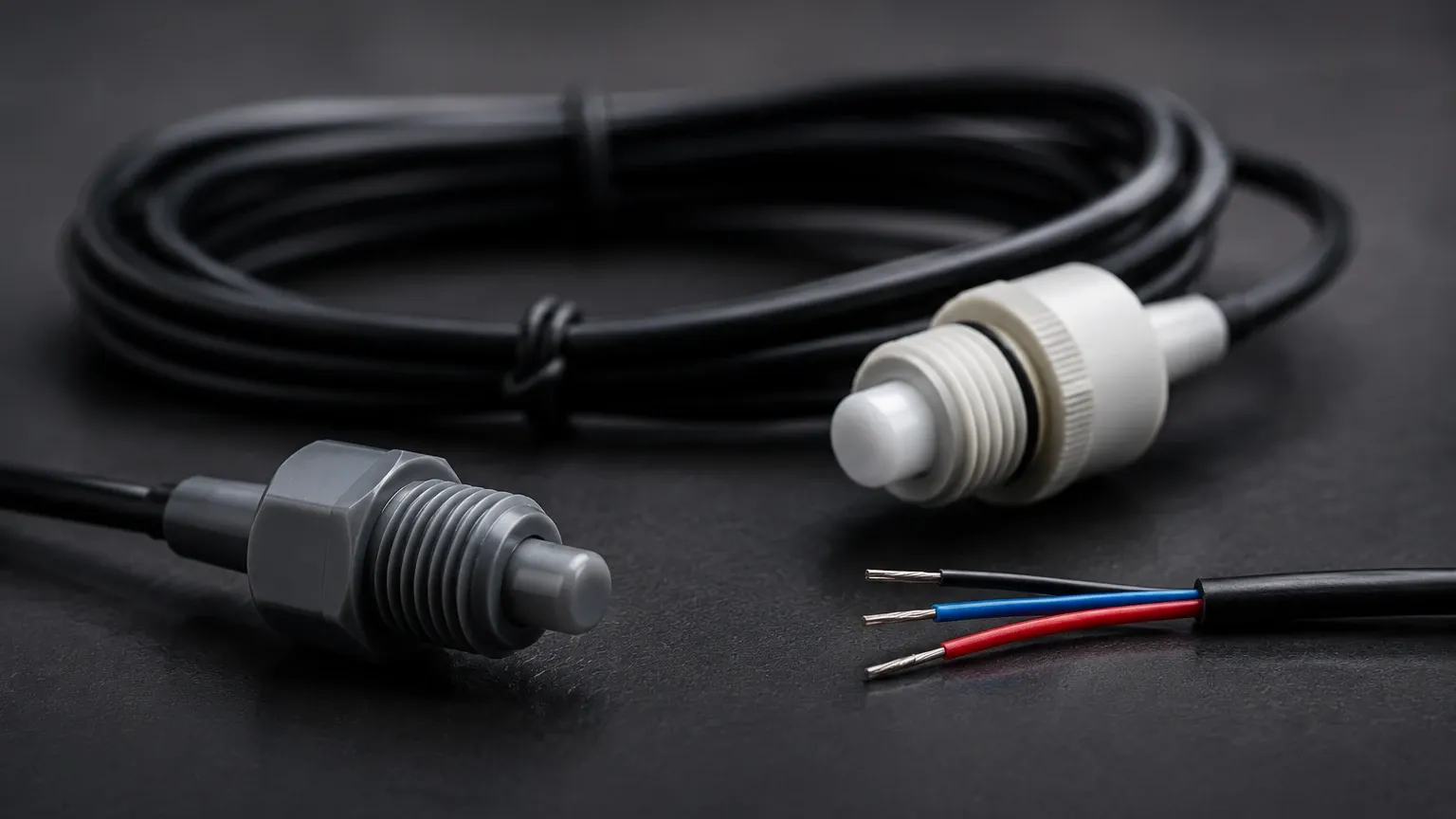
Most 0-5V sensors use a three-wire configuration:
* Red (V+): Power supply (typically 12-24V DC).
* Black (GND): Common ground for both power and signal.
* White/Blue (Signal): The 0-5V output.
Shielding and Grounding
To prevent noise from variable frequency drives (VFDs) or motors, use shielded twisted-pair cabling. The shield should be grounded at only one end (usually the controller side) to prevent ground loops, which can introduce significant errors in a voltage-based measurement.
Cable Length Limitations
Because the signal is a voltage, the resistance of the wire itself causes a voltage drop over long distances. For runs exceeding 15 meters (approx. 50 feet), the 0-5V signal may degrade, leading to inaccurate readings at the controller. In such cases, a 4-20mA transmitter or a digital RS485/Modbus interface is preferred.
Continuous Sensing vs. Point-Level Detection
While a level sensor 0 5v provides a continuous data stream, it is often used in conjunction with point-level devices. Continuous sensors are excellent for inventory management and trend analysis, but for critical safety functions—such as preventing a tank overflow or protecting a pump from running dry—mechanical or electronic switches are often mandated.
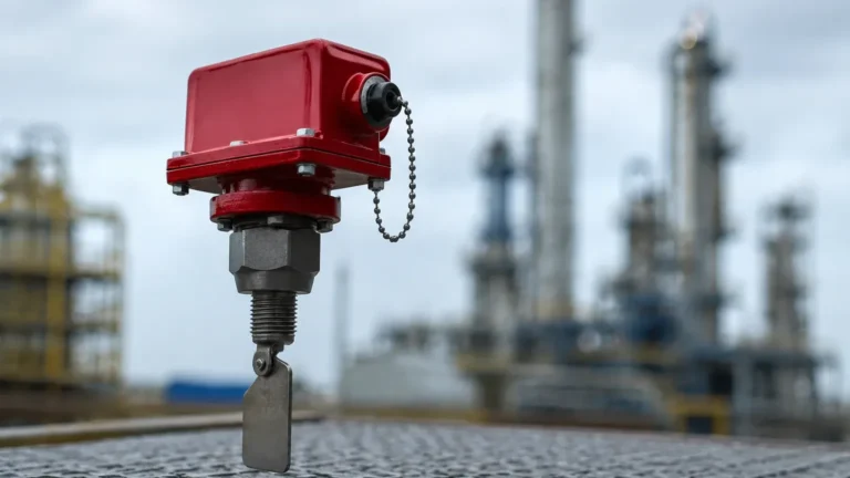
For applications requiring discrete high-level or low-level alarms that operate independently of the continuous monitoring system, industrial Level Switches provide the necessary redundancy. Using a combination of a 0-5V sensor for process control and a dedicated switch for emergency shut-off is a standard best practice in industrial safety engineering.
Limitations and Potential Risks
Despite their versatility, 0-5V sensors have specific limitations that must be addressed during the design phase:
* Signal Zeroing: Unlike a 4-20mA system where 4mA indicates a "live zero" (allowing the system to detect a broken wire), a 0V reading on a 0-5V sensor could mean either the tank is empty or the sensor has failed/lost power. To mitigate this, some engineers specify a 0.5V to 4.5V output range so that 0V clearly indicates a fault.
* Power Supply Stability: The accuracy of the output is often dependent on the stability of the input power. If the supply voltage fluctuates, the output signal may drift. Welk sensors incorporate internal voltage regulation to minimize this effect, but a stable 24V DC industrial power supply is still recommended.
* Environmental Noise: In high-interference environments, the high impedance of voltage inputs can pick up stray RFI/EMI. If the sensor must be installed near heavy machinery, additional filtering or the use of a current-loop transmitter should be considered.
Calibration and Maintenance
To maintain the accuracy of a level sensor 0 5v, periodic calibration is required. This usually involves a two-point calibration process:
1. Zero Calibration: With the tank empty (or the sensor at its reference point), adjust the "Zero" potentiometer or software setting until the output is exactly 0.00V.
2. Span Calibration: Fill the tank to its maximum working level (or apply the equivalent pressure/distance) and adjust the "Span" or "Gain" until the output reaches 5.00V.
Maintenance should include checking the sensor diaphragm for scaling or debris (in hydrostatic models) and ensuring the transducer face is clean (in ultrasonic models). For submersible hydrostatic sensors, the moisture-absorbing desiccant in the vent tube must be replaced regularly to prevent internal condensation.
Frequently Asked Questions (FAQ)
Q: Can I use a 0-5V sensor with a 3.3V microcontroller like an Arduino or ESP32?
A: Yes, but you must use a voltage divider (typically two resistors) to scale the 0-5V signal down to 0-3.3V to avoid damaging the microcontroller's input pins.
Q: What is the difference between 0-5V and 1-5V signals?
A: A 1-5V signal is often used to provide a "live zero." If the controller detects 0V, it knows there is a wiring fault or power loss. If it detects 1V, it knows the sensor is functioning and the tank is at its minimum level.
Q: How does liquid density affect 0-5V hydrostatic sensors?
A: Hydrostatic sensors measure pressure. If the liquid density changes (e.g., switching from water to oil), the pressure at the same height will change. The sensor must be recalibrated for the specific gravity of the new liquid to maintain an accurate 0-5V mapping.
Q: Are 0-5V sensors suitable for outdoor tanks?
A: Yes, provided the sensor has an appropriate Ingress Protection (IP) rating, such as IP65 or IP68. For outdoor ultrasonic sensors, ensure they have sunshields to prevent temperature-induced errors on the transducer face.
By selecting the appropriate technology and following rigorous installation standards, a level sensor 0 5v provides a reliable, cost-effective solution for a wide array of industrial level measurement challenges. Whether monitoring water reservoirs or chemical storage vats, these sensors offer the precision required for modern process automation.