Level Sensor 24v
Level Sensor 24v
In the landscape of industrial automation, the 24V DC power standard is the most prevalent electrical specification for field instrumentation. A level sensor 24v configuration is the backbone of modern process control, providing a reliable, low-voltage interface between physical storage tanks and control systems such as PLCs (Programmable Logic Controllers) or DCS (Distributed Control Systems). Choosing the right sensor involves understanding not just the electrical requirements, but the underlying physics of measurement and how they interact with specific media and environmental conditions.
This guide examines the core technologies, selection criteria, and engineering best practices for implementing 24V level measurement solutions in industrial environments.
Core Measurement Principles
Before selecting a specific instrument, it is essential to understand the physical principles that govern how a level sensor 24v operates. Industrial level measurement is generally categorized into two types: continuous level measurement and point level detection.
Radar Level Measurement
Radar level sensors operate on the Time-of-Flight (ToF) principle. The sensor emits high-frequency microwave pulses (typically in the 26 GHz or 80 GHz range). These pulses travel to the surface of the medium, reflect, and return to the sensor antenna. The instrument calculates the distance based on the time interval between emission and reception. Radar is highly valued because it is non-contact and largely unaffected by changes in temperature, pressure, or vapor space conditions.
Ultrasonic Level Measurement
Similar to radar, ultrasonic sensors use the ToF principle but utilize sound waves instead of electromagnetic waves. A transducer emits an ultrasonic pulse that bounces off the liquid or solid surface. Because sound speed is influenced by air temperature, these sensors usually include an integrated temperature probe to compensate for variations. They are cost-effective for water treatment and simple chemical storage but may struggle in the presence of heavy foam or vacuum conditions.
Hydrostatic Pressure Measurement
Hydrostatic sensors measure the pressure exerted by a liquid column at a specific depth. Based on the formula $P = \rho gh$ (where $P$ is pressure, $\rho$ is density, $g$ is gravity, and $h$ is height), the sensor can determine the level of the liquid. These are typically submersible or externally mounted via a flange. They are highly reliable for vented tanks but require density compensation if the liquid composition changes.
Point Level Detection (Switches)
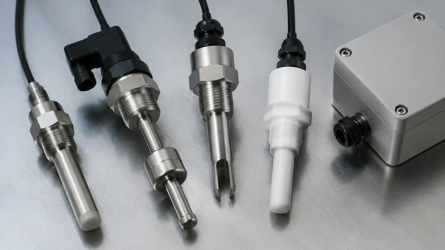
While continuous sensors provide a 0-100% reading, Level Switches are used to detect specific thresholds, such as high-level alarms or dry-run protection for pumps. Common technologies include:
* Vibrating Fork: A piezo-electrically energized fork vibrates at its natural frequency. When immersed in a medium, the frequency shifts, triggering the switch.
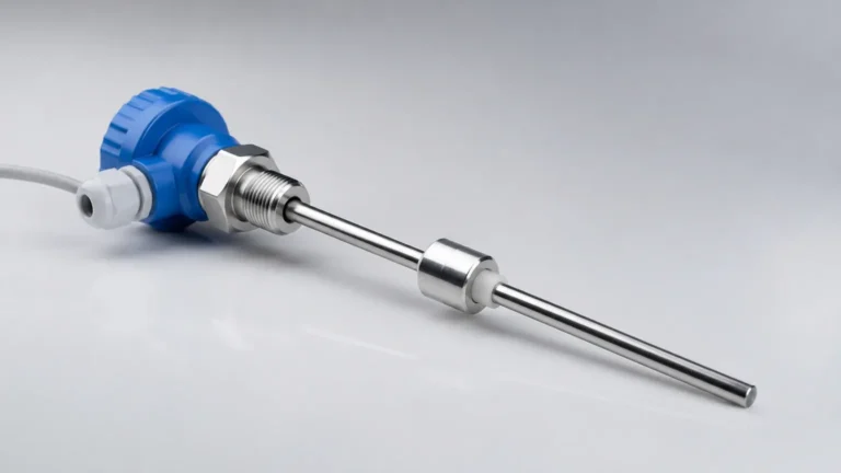
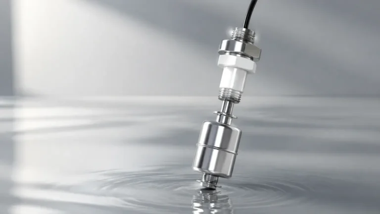
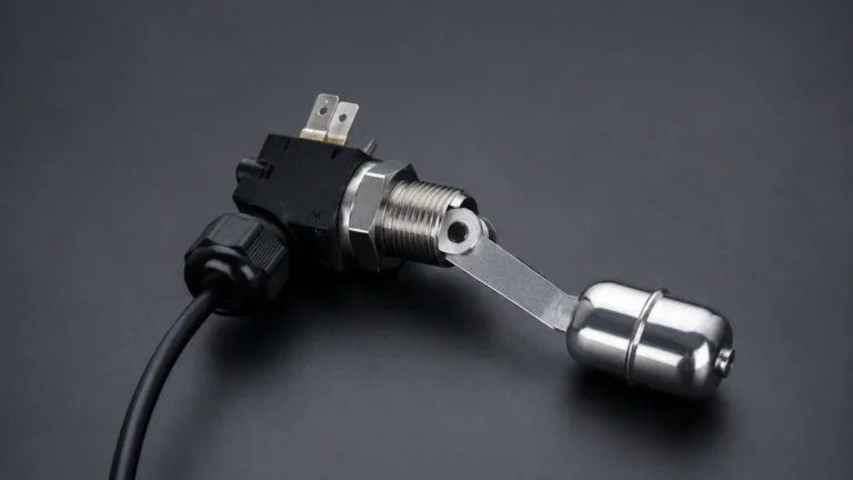
* Float Switches: A magnetic float moves with the liquid level, actuating a reed switch inside a stationary stem.
* Capacitive Switches: These detect a change in capacitance between the sensor probe and the tank wall when the medium is present.
Key Evaluation Criteria for 24V Systems
When specifying a level sensor 24v, engineers must look beyond the voltage rating and evaluate the following technical parameters to ensure long-term reliability.
Output Signal and Communication
Most 24V sensors provide one of the following output types:
* 4-20 mA Analog: The industry standard for continuous measurement. It is robust against electrical noise and can transmit signals over long distances.
* PNP/NPN Transistor: Common for level switches. PNP (sourcing) is standard in Europe and North America, while NPN (sinking) is often found in specific OEM machinery.
* Digital Protocols: Many modern 24V sensors support HART, Modbus RS485, or IO-Link. These protocols allow for remote configuration and diagnostic data transmission.
Media Characteristics
The physical properties of the substance being measured dictate the sensor material and technology. Key factors include:
* Dielectric Constant ($ε_r$): Critical for radar and capacitive sensors. Low dielectric fluids (like oils) reflect less energy than high dielectric fluids (like water).
* Viscosity and Coating: Sticky or viscous fluids can build up on probes. In such cases, non-contact radar or vibrating forks with "coating rejection" features are preferred.
* Chemical Compatibility: The wetted parts (SS316L, PTFE, PP, or PVDF) must be resistant to the process medium to prevent corrosion.
Process Conditions
* Pressure: Ensure the sensor housing and process connection can withstand the maximum operating pressure (e.g., 10 bar, 40 bar).
* Temperature: 24V electronics are sensitive to heat. For high-temperature applications (above 80°C), sensors with integrated cooling fins or remote electronics may be necessary.
Selection Table: Technology Comparison
| Technology | Measurement Type | Accuracy | Best For | Limitations |
| :— | :— | :— | :— | :— |
| 80 GHz Radar | Continuous | ±1 mm | Corrosive liquids, solids, narrow tanks | High initial cost |
| Ultrasonic | Continuous | ±0.25% of range | Water, wastewater, open channels | Affected by foam and wind |
| Hydrostatic | Continuous | ±0.1% to 0.5% | Deep wells, vented tanks | Requires constant density |
| Vibrating Fork | Point (Switch) | ±1 mm | Overfill protection, pump control | Not for extremely viscous media |
| Float Switch | Point (Switch) | ±2-5 mm | Simple water tanks, sumps | Moving parts can jam |
Installation Considerations
Proper installation is as critical as sensor selection. Even the most advanced level sensor 24v will fail to provide accurate data if installed incorrectly.
Wiring and Power Supply
Industrial 24V DC power supplies can fluctuate. It is recommended to use a regulated power supply with a tolerance of ±10%.
* 2-Wire Loop: The sensor receives power and transmits the 4-20 mA signal over the same two wires. This simplifies wiring but limits the power available for the sensor's internal processing.
* 3-Wire/4-Wire: Separate wires are used for power and signal. This is common for sensors with high power requirements, such as certain radar models or those with integrated displays and heaters.
Mounting Position
* Dead Zones (Blocking Distance): Every ultrasonic and radar sensor has a "dead zone" directly below the transducer where measurement is impossible. Ensure the sensor is mounted high enough so the maximum liquid level does not enter this zone.
* Obstructions: Avoid mounting sensors near agitators, fill pipes, or internal tank ladders. These can cause "false echoes" that interfere with the primary signal.
* Nozzle Geometry: For radar sensors, the height and diameter of the mounting nozzle can affect the signal beam. Follow the manufacturer's guidelines regarding nozzle length to prevent signal ringing.
Grounding and Shielding
To prevent electromagnetic interference (EMI) from VFDs (Variable Frequency Drives) and other heavy machinery, always use shielded twisted-pair cables. The shield should be grounded at one end (usually the control cabinet side) to prevent ground loops.
Operational Limitations and Risks
While 24V level sensors are highly versatile, they are not without limitations. Engineers should be aware of the following risks:
1. Voltage Drop: Over long cable runs (e.g., exceeding 300 meters), the resistance of the wire can cause a significant voltage drop. If the voltage at the sensor terminals falls below the minimum operating threshold (typically 12V to 18V DC), the sensor may reboot or provide erratic readings.
2. Foam and Turbulence: Thick foam can absorb ultrasonic and radar signals, leading to a "loss of echo" error. In turbulent tanks, a stilling well (a pipe installed inside the tank) can be used to provide a calm surface for measurement.
3. Condensation and Buildup: In high-humidity environments, condensation can form on the sensor face. While many modern sensors feature "drip-off" antenna designs, heavy buildup of solids or crystallized chemicals can still attenuate the signal.
4. Environmental Sealing: For outdoor or wash-down environments, ensure the sensor has an appropriate IP rating (IP66, IP67, or IP68). Ensure cable glands are properly tightened to prevent moisture ingress into the electronics housing.
Frequently Asked Questions (FAQs)
Q: Can I use a 24V level sensor with a 12V power supply?
A: Generally, no. Most industrial 24V sensors require a minimum of 18V DC to operate correctly. Using a 12V supply will likely result in the device failing to power up or experiencing frequent resets.
Q: What is the difference between a 2-wire and 4-wire level sensor?
A: A 2-wire sensor uses the 4-20 mA loop to both power the device and transmit the signal. A 4-wire sensor has two dedicated wires for 24V DC power and two separate wires for the output signal. 4-wire sensors are used when the device requires more power than the 4 mA baseline can provide.
Q: How do I handle level measurement in a tank with an agitator?
A: Use a sensor with advanced software filtering (false echo suppression) or install the sensor inside a stilling well. Non-contact radar is often the best choice here as it can be programmed to ignore the moving blades of the agitator.
Q: Is a 24V level sensor safe for explosive atmospheres?
A: Only if it is specifically rated as "Intrinsically Safe" (Ex ia) or "Explosion Proof" (Ex d). Intrinsically safe 24V sensors must be used in conjunction with a safety barrier located in the non-hazardous area to limit the energy available to the sensor.
Conclusion
Selecting a level sensor 24v requires a balanced evaluation of the application's physical, chemical, and electrical requirements. By understanding the measurement principles—whether it be the precision of 80 GHz radar or the simplicity of hydrostatic pressure—and adhering to strict installation standards, operators can ensure accurate and maintenance-free level monitoring. For applications requiring simple threshold detection rather than continuous tracking, high-quality Level Switches remain the most reliable choice for safety-critical overfill and dry-run protection.