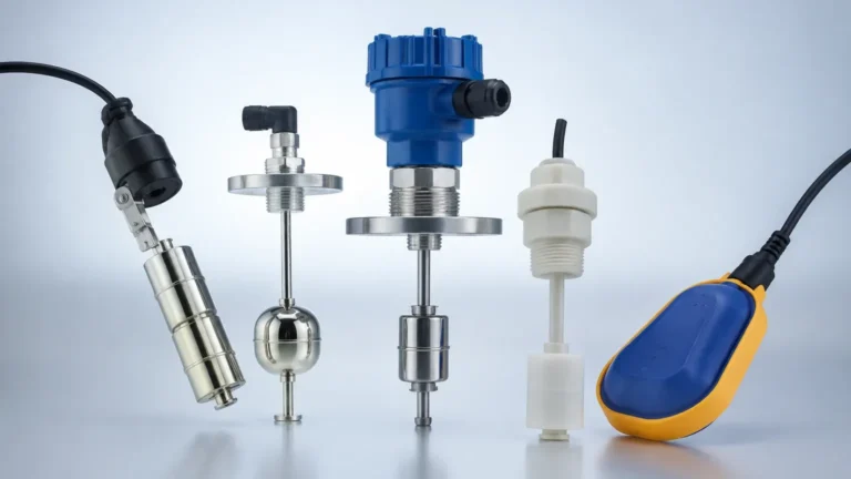
Level Sensor 3 Wire
Level Sensor 3 Wire
In the landscape of industrial automation and process control, the electrical configuration of a measurement device is as critical as its sensing technology. The "level sensor 3 wire" configuration represents a standard interface for both continuous level transmitters and point-level detection devices. Unlike simpler two-wire loop-powered systems, three-wire sensors utilize a dedicated line for the output signal, separate from the power supply, while sharing a common ground. This architecture is particularly prevalent in systems requiring higher power consumption or specific output types like 0–10 VDC or NPN/PNP transistor logic.
For engineers and procurement specialists, selecting the correct wiring format is essential for compatibility with Programmable Logic Controllers (PLCs) and Distributed Control Systems (DCS). This guide examines the principles, selection criteria, and installation requirements for three-wire level instruments.
Understanding the 3-Wire Configuration in Level Measurement
A level sensor 3 wire setup is defined by its electrical connectivity. In this arrangement, the device is powered by two wires (typically positive and negative DC voltage), and the third wire carries the output signal. The negative power lead usually doubles as the reference or common ground for the signal wire.
The Wiring Logic
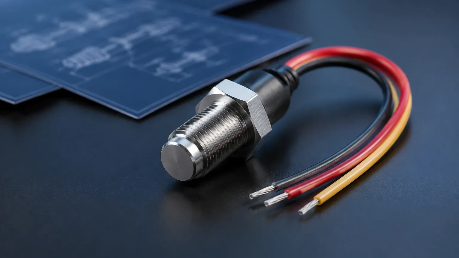
1. V+ (Brown/Red): The positive DC power supply, usually ranging from 12V to 36V DC.
2. 0V/Common (Blue/Black): The return path for the power supply and the reference point for the signal.
3. Signal Out (White/Black): The output wire providing either a continuous analog voltage (e.g., 0–5V, 0–10V) or a digital switching state (NPN or PNP).
This configuration is distinct from 2-wire sensors, which must operate on the residual current of the 4–20 mA loop (typically < 3.5 mA), and 4-wire sensors, which feature fully isolated power and signal circuits. The 3-wire design offers a middle ground, providing enough power for advanced electronics—such as those found in high-frequency radar or heated ultrasonic transducers—without the complexity of a four-wire installation.
Measurement Principles for 3-Wire Level Instruments
Three-wire configurations are found across various sensing technologies. The choice of technology depends on the physical properties of the medium being measured, such as dielectric constant, density, and turbulence.
Ultrasonic Level Sensors
Ultrasonic sensors emit high-frequency sound pulses that reflect off the surface of the liquid or solid. The time-of-flight is measured to calculate the distance. Because the internal processing and the transducer's pulse generation require significant peak power, many ultrasonic units are designed as 3-wire devices to ensure stable performance without the current limitations of a 2-wire loop.
Radar Level Meters
Non-contact radar (60GHz or 80GHz) uses electromagnetic waves to detect level. While many modern radar units are optimized for 2-wire 4–20 mA loops, 3-wire versions are often used when a voltage output (0–10V) is required for specific PLC analog input cards or when integrated displays and wireless modules demand higher power.
Point-Level Switches
In point-level detection, Level Switches frequently utilize a 3-wire DC configuration. These are commonly used for high-level alarms or pump control. The output is typically a transistor signal:
* PNP (Sourcing): The switch connects the signal wire to the positive supply (V+) when triggered.
* NPN (Sinking): The switch connects the signal wire to the common ground (0V) when triggered.
Key Differences: 2-Wire vs. 3-Wire vs. 4-Wire Systems
Choosing between these configurations involves balancing wiring costs, power requirements, and signal integrity. The following table highlights the primary distinctions.
| Feature | 2-Wire (Loop Powered) | 3-Wire (DC) | 4-Wire (Isolated) |
| :— | :— | :— | :— |
| Power Source | From the signal loop | Dedicated DC supply | Independent AC or DC |
| Output Type | 4–20 mA only | 0–10V, 4–20 mA, NPN/PNP | 4–20 mA, Relays, RS485 |
| Wiring Cost | Lowest | Moderate | Highest |
| Power Availability | Limited (< 3.5 mA for electronics) | High | Very High |
| Common Ground | Yes (Signal is the power) | Yes (Signal shares 0V) | No (Fully isolated) |
| Typical Use | Standard industrial loops | OEM machinery, PLCs | High-power radar, heated probes |
Selection Criteria for 3-Wire Level Sensors and Switches
When specifying a level sensor 3 wire device, engineers must look beyond the measurement range and consider the electrical environment of the application.
1. Output Signal Compatibility
If the control system requires a voltage input (e.g., 0–10V), a 3-wire sensor is the standard choice. For digital switching, one must confirm whether the PLC input is "active high" (requiring a PNP switch) or "active low" (requiring an NPN switch). Selecting the wrong polarity will prevent the system from registering the level state.
2. Supply Voltage and Current Consumption
Most 3-wire sensors operate on 24V DC. However, in mobile equipment or battery-powered remote stations, sensors that can operate at 12V DC are required. It is also important to check the current consumption (measured in mA) to ensure the power supply is not overloaded, especially when multiple sensors are connected to the same rail.
3. Environmental Resistance
Industrial environments often involve moisture, dust, and corrosive chemicals. For 3-wire installations, the ingress protection (IP) rating is paramount. An IP67 or IP68 rating is recommended for tanks where splashing or submersion is possible. Furthermore, the cable material (PVC, PUR, or Teflon) must be compatible with the process media to prevent insulation failure and short circuits.
4. Response Time and Hysteresis
For level switches, the response time (how fast the switch reacts to the liquid) and hysteresis (the difference between the switch-on and switch-off points) are critical for preventing "chatter" in pump control applications. Many 3-wire electronic switches allow for adjustable delay times to filter out surface turbulence.
Installation and Wiring Best Practices
Proper installation is the most effective way to prevent signal noise and premature device failure. Follow these engineering guidelines when deploying 3-wire level instruments.
Wiring and Grounding
* Shielded Cables: Always use shielded cables for 3-wire sensors, especially in environments with high electromagnetic interference (EMI) from motors or variable frequency drives (VFDs). The shield should be grounded at the control cabinet end only to avoid ground loops.
* Common Grounding: Ensure that the 0V/Common wire is securely connected to the same reference as the PLC's analog or digital input card. A floating ground in a 3-wire system can lead to erratic readings or "ghost" signals.
* Voltage Drop: For long cable runs exceeding 50 meters (164 ft), calculate the voltage drop. While 3-wire systems are less sensitive to resistance than 2-wire loops, a significant drop in the supply voltage can cause the sensor to reboot or provide inaccurate voltage outputs.
Mounting Considerations
* Dead Zones: For ultrasonic and radar 3-wire sensors, ensure the device is mounted above the maximum possible liquid level, respecting the "dead zone" or "blocking distance" (typically 0.2 m to 0.5 m or 0.66 ft to 1.64 ft).
* Nozzle Geometry: If mounting on a tank nozzle, the diameter and height of the nozzle must not interfere with the sensor’s signal beam. Internal obstructions like ladders or agitators should be mapped out during commissioning.
* Switch Orientation: For point-level Level Switches, ensure the sensing element is positioned where it will not be affected by the fill stream, which could cause false triggers.
Common Applications and Limitations
Applications
* Mobile Machinery: 3-wire sensors are the standard for hydraulic oil tanks and fuel levels in construction and agricultural equipment due to the availability of DC power.
* Water Treatment: Used in chemical dosing tanks where 0–5V or 0–10V signals are preferred for simple controller interfaces.
* Food and Beverage: 3-wire capacitive switches are used for detecting the presence of liquids in pipes or small buffer tanks.
Limitations
* Lack of Isolation: Because the signal and power share a common ground, 3-wire sensors are more susceptible to electrical noise if the power supply is shared with noisy loads like large solenoids or relays.
* Wiring Complexity: Compared to 2-wire systems, 3-wire setups require 50% more copper and terminal space, which can increase costs in large-scale installations with hundreds of points.
* Safety Barriers: In hazardous areas (Ex zones), 3-wire sensors are more complex to protect with Zener barriers or galvanic isolators compared to standard 2-wire intrinsically safe loops.
Frequently Asked Questions (FAQs)
Q: Can I convert a 3-wire NPN sensor to a PNP output?
A: Not directly through wiring alone. NPN and PNP refer to the internal transistor architecture. You would need an external relay or a signal converter module to invert the logic.
Q: What happens if I reverse the polarity on a 3-wire level sensor?
A: Most high-quality industrial sensors, such as those from Welk, include reverse polarity protection. However, if the sensor lacks this feature, reversing the V+ and 0V wires can permanently damage the internal circuit board.
Q: Can a 3-wire sensor provide a 4–20 mA signal?
A: Yes. While 4–20 mA is traditionally associated with 2-wire loops, many 3-wire sensors output a 4–20 mA signal where the current is sourced from the dedicated power supply rather than the loop itself. This is often referred to as an "active" current signal.
Q: Is a 3-wire sensor better than a 2-wire sensor for accuracy?
A: Not necessarily. Accuracy is determined by the sensing technology (e.g., radar vs. ultrasonic) and the quality of the electronics. The 3-wire configuration simply provides more power for the sensor's functions, which can be beneficial for complex signal processing in difficult environments.
Summary of Selection
| Application Requirement | Recommended Configuration |
| :— | :— |
| High-speed switching (NPN/PNP) | 3-Wire DC |
| Voltage Output (0–10V) | 3-Wire DC |
| Long-distance signal (4–20 mA) | 2-Wire (Preferred) or 3-Wire |
| Battery/Solar Power | 2-Wire (Low Power) |
| High EMI Environment | 4-Wire (Isolated) |
Selecting a level sensor 3 wire instrument requires a clear understanding of the electrical interface and the process demands. By ensuring compatibility between the sensor's output and the control system's input, and by following rigorous installation standards, operators can achieve reliable and accurate level monitoring across a wide range of industrial applications.