Level Sensor 2 Wire
Level Sensor 2 Wire
In the landscape of industrial automation and process control, the "2-wire" configuration has become the global standard for transmitting analog signals. A level sensor 2 wire setup, often referred to as a loop-powered system, integrates power supply and signal transmission into a single pair of conductors. This architecture significantly reduces installation costs, simplifies wiring complexity, and enhances reliability in demanding environments such as water treatment, chemical processing, and oil and gas storage.
For engineers and procurement specialists, understanding the nuances of 2-wire technology is essential for selecting the right instrumentation. This guide explores the fundamental principles, technological variations, and practical selection criteria for 2-wire level measurement solutions.
Fundamentals of 2-Wire Measurement Principles
The core principle of a level sensor 2 wire system is the 4-20 mA current loop. In this configuration, the sensor acts as a variable resistor controlled by the measured process variable (the liquid or solid level).
The 4-20 mA Loop Mechanism
A DC power supply (typically 24V DC) provides the energy for the circuit. The level sensor is connected in series with the power supply and the receiving device (such as a PLC, DCS, or digital indicator). The sensor regulates the current flowing through the loop:
* 4 mA represents the 0% or minimum level (Lower Range Value – LRV).
* 20 mA represents the 100% or maximum level (Upper Range Value – URV).
Because the sensor must operate even at the 4 mA signal level, it is designed with extremely low power consumption. This "live zero" at 4 mA also serves as a diagnostic tool; if the current drops to 0 mA, the system immediately recognizes a wire break or power failure.
Comparison: 2-Wire vs. 3-Wire and 4-Wire Systems
| Feature | 2-Wire (Loop Powered) | 3-Wire | 4-Wire (Self-Powered) |
| :— | :— | :— | :— |
| Wiring | One pair for power & signal | Three wires (Common, Power, Signal) | Two pairs (One for power, one for signal) |
| Power Source | From the signal loop | External DC supply | External AC or DC supply |
| Installation Cost | Lowest | Moderate | Highest |
| Power Availability | Limited (< 4mA for electronics) | Moderate | High (for heaters/backlights) |
| Typical Use | Standard process transmitters | High-power ultrasonic/radar | Heavy-duty industrial/high-heat |
Common Technologies Using 2-Wire Configurations
Modern level measurement instruments, such as those manufactured by Welk, utilize 2-wire architecture across various sensing technologies. Each technology has specific advantages depending on the medium and environmental conditions.
1. Radar Level Meters
2-wire radar level meters use either Pulse Radar or Frequency Modulated Continuous Wave (FMCW) technology. These are non-contact sensors ideal for corrosive or high-temperature liquids. The challenge in 2-wire radar design is managing the high-frequency microwave generation within the strict power limits of a 4-20 mA loop. Advanced electronics allow these sensors to provide high accuracy (up to ±2 mm) while drawing minimal current.
2. Ultrasonic Level Sensors
Ultrasonic sensors emit sound pulses that reflect off the surface of the material. In a level sensor 2 wire format, these are frequently used in open-channel flow and wastewater tanks. While 2-wire ultrasonic sensors are efficient, they may have limitations in extremely deep tanks or dusty environments where higher acoustic power (often requiring 4-wire setups) would be necessary to penetrate interference.
3. Hydrostatic Level Transmitters
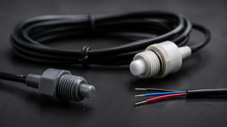
Hydrostatic sensors measure the pressure exerted by a liquid column. These are almost exclusively 2-wire devices. A submersible pressure transducer is lowered into the liquid, and the 2-wire cable includes a vent tube to compensate for atmospheric pressure changes. This ensures that the sensor only measures the head pressure of the liquid.
4. Level Switches
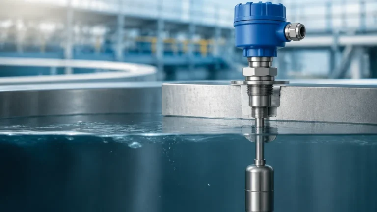
While many people associate 2-wire with continuous measurement, Level Switches also utilize 2-wire configurations, particularly in NAMUR-compliant circuits or when replacing traditional mechanical floats with electronic point-level detection. These switches change their current consumption (e.g., 8 mA for "off" and 16 mA for "on") to signal the state change to a control system.
Practical Selection Criteria for 2-Wire Sensors
Selecting a level sensor 2 wire involves more than just choosing a measurement technology. Engineers must evaluate the electrical and physical constraints of the application.
Electrical Load and Loop Voltage
The most common mistake in 2-wire installations is failing to account for the total loop resistance. The power supply must overcome the combined voltage drop of:
1. The sensor's minimum operating voltage (typically 10V to 12V DC).
2. The voltage drop across the load resistor (usually 250 ohms for a 1-5V conversion at the PLC).
3. The resistance of the wire run (significant over long distances).
Calculation Example:
If a sensor requires 12V min, and the PLC has a 250Ω resistor:
* Voltage drop at 20 mA = $0.020 A \times 250 Ω = 5V$.
* Required Supply = $12V (Sensor) + 5V (PLC) + 1V (Wire margin) = 18V DC$.
* A standard 24V DC supply is usually sufficient, but long cable runs may require higher voltage or lower resistance wire.
Medium Properties
* Dielectric Constant (εr): Critical for radar sensors. Low dielectric liquids (like oils) reflect less energy, requiring more sensitive 2-wire electronics.
* Density: Critical for hydrostatic sensors. If the liquid density changes due to temperature, the 2-wire pressure reading will lose accuracy unless compensated.
* Corrosiveness: Ensure the wetted parts (316L Stainless Steel, PTFE, or PVDF) are compatible with the process media.
Installation and Wiring Considerations
To ensure the longevity and accuracy of a level sensor 2 wire, follow these engineering best practices:
1. Shielding and Grounding: Use twisted-pair shielded cable to prevent Electromagnetic Interference (EMI) from VFDs and motors. The shield should be grounded at only one point (usually the control room end) to avoid ground loops.
2. Cable Length: While 4-20 mA signals can travel over 1,000 meters (3,280 feet), signal degradation can occur if the wire gauge is too thin. Use 18 AWG (0.82 mm²) or 16 AWG (1.31 mm²) for long runs.
3. Environmental Sealing: Level sensors are often installed in humid or outdoor environments. Ensure the conduit entries are sealed with appropriate glands to prevent moisture from entering the electronics housing through capillary action.
4. Intrinsic Safety: In hazardous areas (Class I, Div 1 or ATEX Zone 0), 2-wire sensors are preferred because they can be easily used with Zener barriers or galvanic isolators to limit the energy entering the explosive atmosphere.

Limitations of 2-Wire Systems
Despite their versatility, 2-wire level sensors have specific limitations:
* Power Constraints: Features like internal heaters (for preventing condensation on radar lenses) or high-intensity backlit displays often require more power than a 4-20 mA loop can provide. In these cases, a 4-wire sensor is necessary.
* Response Time: Some 2-wire ultrasonic or radar sensors may have a slightly slower response time (update rate) compared to 4-wire versions because they need time to charge internal capacitors between measurement cycles.
* Signal Noise: While current loops are robust, extremely high-noise environments can still affect the signal if proper shielding is not implemented.
Frequently Asked Questions (FAQ)
Q: Can I use a 2-wire sensor with a 4-wire PLC input?
A: Yes. You will need to provide an external 24V DC power supply in series with the sensor and the PLC input. This is a common configuration when the PLC does not provide loop power.
Q: What is the difference between a "passive" and "active" 2-wire sensor?
A: In industry terms, a 2-wire sensor is almost always "passive," meaning it requires an external power source to drive the loop. An "active" transmitter would provide its own power, which effectively makes it a 4-wire device (even if it only uses two wires for the signal).
Q: How do I calibrate a 2-wire level sensor?
A: Most modern 2-wire sensors are calibrated via HART (Highway Addressable Remote Transducer) protocol, which superimposes a digital signal on top of the 4-20 mA analog loop. Alternatively, many units feature local push-buttons and an LCD for zero and span adjustment.
Q: Can a 2-wire level sensor measure solids?
A: Yes, 2-wire radar and ultrasonic sensors are frequently used for grain, plastic pellets, and minerals. However, the internal signal processing must be specifically configured for the uneven surfaces and low reflectivity of solids.
Conclusion
The level sensor 2 wire remains the backbone of process level measurement due to its efficiency and cost-effectiveness. By understanding the electrical requirements of the 4-20 mA loop and matching the sensing technology to the specific application, engineers can ensure reliable data for their automation systems. Whether utilizing radar for chemical tanks or hydrostatic pressure for water reservoirs, Welk provides robust 2-wire solutions designed to meet the rigors of modern industrial environments.
For applications requiring point-level detection rather than continuous measurement, exploring specialized Level Switches can provide a simplified and highly reliable alternative within the same 2-wire infrastructure.