Switches Typically Operate Within Which Osi Level
Switches Typically Operate Within Which Osi Level
In the realms of both information technology and industrial automation, the term "switch" is foundational, yet its meaning shifts depending on the context. For network engineers, the question of switches typically operate within which osi level is a fundamental architectural query. For process engineers and plant managers, a "switch" is more likely a point-level detection device used to prevent tank overflows or pump dry-running.
Understanding the intersection of these two worlds is increasingly critical as Industry 4.0 integrates physical sensors into digital networks. This article clarifies the functional levels of networking switches and provides a comprehensive engineering guide to industrial Level Switches, their measurement principles, and their selection in modern process environments.
The Networking Perspective: OSI Layer Operations
To answer the technical query: in a standard networking context, switches typically operate within the Data Link Layer, which is Layer 2 of the Open Systems Interconnection (OSI) model.
Layer 2 Switches (Data Link)
Traditional Ethernet switches operate at Layer 2. They use Hardware (MAC) addresses to direct data to the specific port where the destination device is connected. This increases efficiency compared to a hub, which broadcasts data to all ports. In an industrial plant, a Layer 2 switch might connect several level sensors to a local Programmable Logic Controller (PLC).
Layer 3 Switches (Network)
More advanced switches, known as multilayer switches, operate at Layer 3 (the Network Layer). These devices can perform routing functions using IP addresses. In large-scale industrial automation, Layer 3 switches are used to manage traffic between different subnets, such as moving data from the production floor (OT) to the corporate office (IT).
The Industrial "Layer 0"
While networking switches move data, industrial level switches operate at what we might call "Layer 0"—the physical process interface. These devices detect the presence or absence of material at a specific height and convert that physical state into an electrical signal that the Layer 2 and Layer 3 network infrastructure eventually carries.
Principles of Industrial Level Measurement
Before selecting a device, it is essential to understand the physics behind point-level detection. Unlike continuous level transmitters that provide a 4-20mA or digital percentage of a tank's volume, level switches are binary devices (on/off). They are primarily used for high-level alarms, low-level alarms, or pump control.
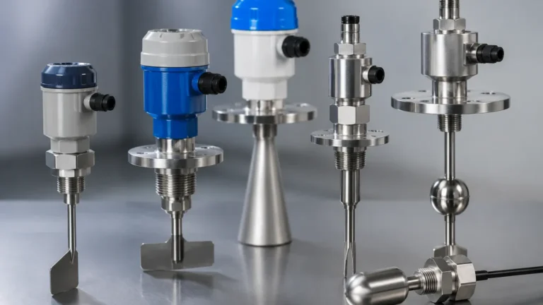
1. Vibrating (Tuning Fork) Principle
The sensor consists of two tines that are vibrated at their natural resonant frequency by a piezoelectric crystal. When the tines are covered by a liquid or solid, the frequency changes or the vibration is damped. The electronics detect this shift and trigger the switch output. This method is highly resistant to changes in pressure, temperature, and conductivity.
2. Float and Magnetic Principle
This is one of the most established technologies. A float containing a magnet moves with the liquid level along a stem. Inside the stem, a reed switch is hermetically sealed. When the float’s magnet reaches the reed switch, the circuit closes or opens. It is a simple, mechanical solution that requires no external power for the sensing element itself.
3. Capacitive Principle
Capacitance switches operate based on the dielectric constant of the material being measured. The sensor probe and the tank wall (or a reference electrode) act as two plates of a capacitor. As the material covers the probe, the capacitance increases. Once a pre-set threshold is reached, the switch state changes. This is effective for both liquids and solids but can be sensitive to material buildup on the probe.
4. Ultrasonic Principle
Ultrasonic point-level switches utilize a gap in the sensor head. An ultrasonic signal is transmitted across the gap. When the gap is filled with liquid, the signal is transmitted efficiently; when it is filled with air or gas, the signal is attenuated. This is ideal for non-contact or minimally invasive detection in clean liquids.
Selection Criteria for Industrial Applications
Choosing the correct instrument requires an analysis of the media properties and the environmental conditions. The following table provides a general guideline for technology selection.
| Medium Type | Recommended Technology | Key Advantage | Limitations |
| :— | :— | :— | :— |
| Clean Liquids | Float / Tuning Fork | High reliability, low cost | Float can jam if debris is present |
| Viscous/Sticky Liquids | Tuning Fork (Coated) | Ignores minor buildup | Extreme coating may cause false trips |
| Corrosive Chemicals | PTFE-Coated Capacitance | Chemical resistance | Requires calibration to the specific media |
| Granular Solids | Vibrating Rod / Rotary | Robust mechanical design | High mechanical stress on the probe |
| Non-Conductive Oils | Capacitance / Ultrasonic | High sensitivity | Sensitive to dielectric changes |
| Hygienic (Food/Pharma) | Hygienic Tuning Fork | Easy to clean (CIP/SIP) | Must meet 3A or EHEDG standards |
Installation Considerations and Best Practices
Correct installation is as vital as selecting the right technology. Even the most advanced switch will fail if placed in a turbulent zone or near a fill stream.
1. Avoid the Fill Stream: Never install a level switch directly under a fill pipe. The falling material will cause false high-level alarms or mechanical damage to the sensor.
2. Mounting Orientation: Tuning forks are typically mounted horizontally for high/low alarms. Float switches can be mounted vertically or horizontally depending on the design. For horizontal mounting, ensure the tines of a tuning fork are oriented vertically so that liquid can easily drain off them.
3. Turbulence and Agitation: If the tank has an agitator, use a stilling well for float switches or choose a non-mechanical technology like a tuning fork that is less affected by moving fluid.
4. Nozzle Length: Ensure the active part of the sensor (the tines or the probe) extends sufficiently into the vessel. If the nozzle is too long, material may get trapped in the "dead zone," leading to a failure to reset.
5. Wiring and Grounding: In industrial environments, electromagnetic interference (EMI) is common. Use shielded cables and ensure the instrument is properly grounded to the vessel to prevent signal noise, especially for capacitive and ultrasonic models.

Limitations and Operational Constraints
While level switches are robust, they have inherent limitations:
* Point Detection Only: They cannot tell you how much material is in a tank, only that it has reached a specific point. For volume tracking, a radar or ultrasonic transmitter is required.
* Media Specificity: A capacitive switch calibrated for water may not work for oil without recalibration due to the difference in dielectric constants.
* Mechanical Wear: Float switches and rotary paddles have moving parts that will eventually wear out, particularly in abrasive or corrosive environments.
* Pressure and Temperature: Most switches have specific ratings (e.g., up to 40 bar or 150°C). Exceeding these can lead to seal failure or electronic malfunction.
Frequently Asked Questions (FAQ)
Q: Can a Layer 2 networking switch be used in a hazardous area?
A: Standard IT switches cannot. However, industrial-grade switches with ATEX or IECEx certifications are available for installation in Zone 1 or Zone 2 environments, often housed in explosion-proof enclosures.
Q: What is the difference between a "Normally Open" (NO) and "Normally Closed" (NC) level switch?
A: This refers to the state of the electrical circuit when the switch is in its "rest" position (usually when not in contact with the material). For safety-critical applications like high-level overflow prevention, a "Normally Closed" configuration is often preferred because a wire break will trigger an alarm (fail-safe).
Q: How do I handle foam in a liquid level application?
A: Foam can be problematic. Tuning forks can often be tuned to ignore light foam and only detect the liquid phase. Capacitance switches may struggle unless the foam has a significantly different dielectric constant than the liquid.
Q: Why would I choose a tuning fork over a float switch?
A: Tuning forks have no moving parts to jam or wear out. They are also generally more compact and less affected by changes in liquid density or the presence of small particulates.
Conclusion
Whether you are troubleshooting a network and asking switches typically operate within which osi level (Layer 2/3) or designing a process safety system using industrial Level Switches, the core objective remains the same: the reliable transfer of critical information. In the modern factory, the physical switch at the tank wall and the digital switch in the server rack work in tandem to ensure operational safety and data integrity. By understanding the measurement principles and selection criteria detailed above, engineers can ensure their systems remain both physically and digitally robust.
Download Switches Typically Operate Within Which Osi Level as a PDF