Floatless Level Switch 61f G
Floatless Level Switch 61f G
In the realm of industrial automation and fluid management, the reliability of point-level detection is paramount. Among the various technologies available, the floatless level switch 61f g remains a cornerstone for conductive liquid applications. Unlike traditional mechanical float switches that rely on moving parts and buoyancy, floatless systems utilize the electrical conductivity of the liquid itself to complete a circuit. This design significantly reduces maintenance requirements and eliminates the risk of mechanical failure due to debris or coating.
As a specialized category within the broader field of Level Switches, the 61F-G series is widely adopted in water treatment, building automation, and industrial processing. This guide provides a comprehensive technical analysis of its measurement principles, selection criteria, and installation best practices to assist engineers in optimizing their level control systems.
Measurement Principle: The Conductivity Method
The floatless level switch 61f g operates on the principle of liquid conductivity. The system consists of a controller (the electronic relay unit) and a set of electrodes (probes) that are inserted into the vessel.
1. The Circuitry: The controller applies a low-voltage AC signal (typically 8V or 24V AC) to the electrodes. Using AC instead of DC is critical to prevent electrolysis and the subsequent corrosion of the electrode surfaces.
2. Detection: When the liquid level rises and touches the electrodes, it completes an electrical path between the "long" common electrode and the "short" detection electrode.
3. Output: The controller detects the resulting current flow and activates an internal electromagnetic relay. This relay can then be used to trigger pumps, valves, or alarms.
By using multiple electrodes of varying lengths, the system can provide multi-point control, such as starting a pump at a high level and stopping it at a low level to prevent frequent cycling (hysteresis).
Technical Specifications of the 61F-G Series
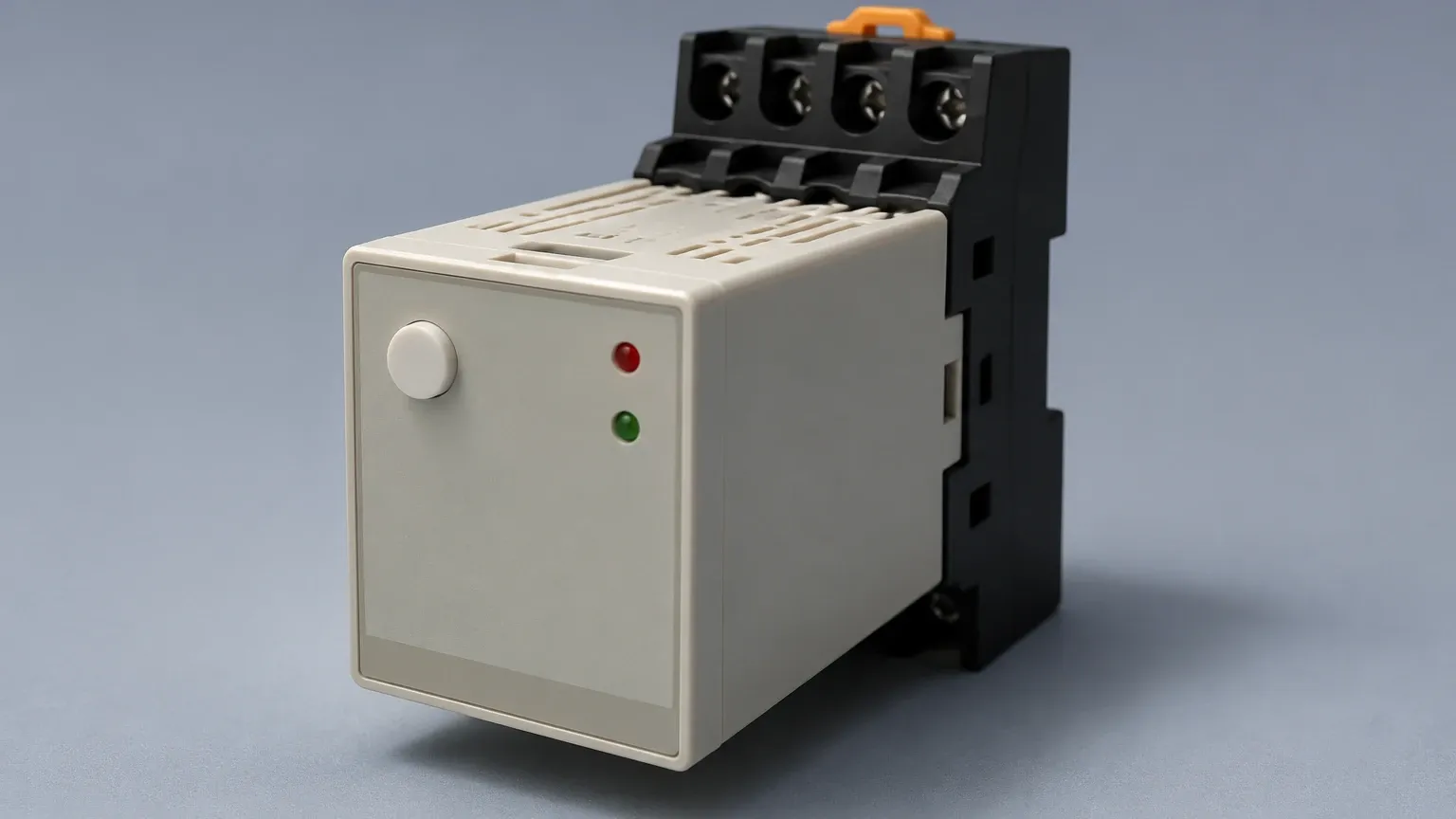
The "G" designation in the 61F series typically refers to the basic model designed for automatic water supply and drainage control. It is often used in conjunction with a 3-pole electrode holder.
Key Parameters
| Parameter | Specification (Standard Model) |
| :— | :— |
| Supply Voltage | 110/220V AC (50/60 Hz) |
| Inter-electrode Voltage | 8V AC |
| Power Consumption | Approx. 3.5 VA |
| Response Time | Operate: 80 ms max; Release: 160 ms max |
| Control Output | 5A at 250V AC (Resistive Load) |
| Ambient Temperature | -10°C to +55°C |
| Insulation Resistance | 100 MΩ min. (at 500V DC) |
Variants and Functional Differences
While the standard floatless level switch 61f g is the most common, the series includes several specialized versions tailored for specific industrial requirements:
* 61F-G1: Designed for automatic water supply with an integrated high-level alarm.
* 61F-G2: Designed for automatic water supply and drainage with an integrated low-level alarm or dry-run protection.
* 61F-G3: Provides automatic water supply/drainage with high-level and low-level alarms.
* 61F-G4: Features automatic water supply and drainage with level indicators and dry-run prevention.
Selection Criteria and Practical Table
Choosing the right configuration for a floatless level switch 61f g requires an evaluation of the liquid characteristics and the tank environment. The most critical component to select after the controller is the electrode material.
Electrode Material Selection
| Material | Application Environment |
| :— | :— |
| Stainless Steel (SUS304/316) | Standard purified water, tap water, and mild industrial wastewater. |
| Titanium | Highly corrosive liquids, seawater, and concentrated acids. |
| Hastelloy | Extreme chemical environments where stainless steel fails. |
Sensitivity Selection
The conductivity of liquids varies significantly. Controllers are often available in different sensitivity ranges:
* Standard Sensitivity: For general tap water and well water (0 to 4 kΩ inter-electrode resistance).
* High Sensitivity: For distilled water or pure water with low conductivity (up to 40 kΩ or higher).
* Low Sensitivity: For liquids with high conductivity or where condensation may cause false triggering (e.g., salt water).
Installation Considerations
Proper installation is vital to ensure the longevity and accuracy of the level switch system. Engineers should adhere to the following guidelines:
1. Electrode Length and Spacing
Electrodes should be cut to the required lengths based on the desired control levels. In deep tanks or areas with high turbulence, electrodes can sway and touch each other, causing short circuits.
* Metric Tip: Use electrode spacers (separators) every 1,000 mm (1 meter) to maintain consistent gaps between the rods.
2. Wiring and Distance
The distance between the controller and the electrodes can impact performance. Long cable runs increase the capacitance of the wiring, which may lead to "leakage current" and false activation.
* If the distance exceeds 50 meters, use a low-sensitivity controller or shielded cable to mitigate capacitance issues.
3. Avoiding Interference
Do not run electrode signal wires in the same conduit as high-voltage power lines. Electromagnetic interference (EMI) from large motors or variable frequency drives (VFDs) can induce noise in the low-voltage electrode circuit.
4. Mounting the Controller
The 61F-G controller is typically DIN-rail mounted or surface-mounted inside an electrical panel. Ensure the panel is well-ventilated and protected from direct moisture, even if the electrodes are in a wet environment.
Application Engineering: Supply vs. Drainage
The wiring logic of the floatless level switch 61f g changes depending on whether the goal is to fill a tank (supply) or empty a tank (drainage).
* Automatic Water Supply: The relay energizes the pump when the water level falls below the lowest electrode (E2) and de-energizes when it reaches the upper electrode (E1). This prevents the pump from cycling too frequently.
* Automatic Drainage: The relay energizes the pump when the water reaches the upper electrode (E1) to prevent overflow and shuts it off once the level drops below the lower electrode (E2).
Limitations and Risks
While highly effective, the floatless level switch 61f g is not a universal solution. Engineers must be aware of its inherent limitations:
1. Non-Conductive Liquids: This technology will not work with oils, diesel, pure hydrocarbons, or highly purified deionized water, as these fluids do not conduct electricity.
2. Coating and Scaling: If the liquid leaves a conductive residue or scale on the electrode spacers, it can create a "bridge" between electrodes, leading to false "high level" readings even when the tank is empty.
3. Turbulence: In tanks with heavy agitation, the liquid surface may bounce against the electrodes, causing relay chatter. In such cases, a time-delay relay or a stilling well (a pipe around the electrodes) should be used.
4. Solid Debris: Large solids in wastewater can physically damage the electrodes or cause tangling if cable-type electrodes are used instead of rigid rods.
Maintenance and Troubleshooting
One of the primary advantages of the floatless system is its minimal maintenance. However, periodic checks are recommended:
* Electrode Cleaning: In wastewater applications, grease or scale can build up on the probe tips. Clean the electrodes with a light abrasive or cloth every 6 to 12 months.
* Check for Corrosion: Even stainless steel can corrode over years of service in harsh water. Inspect the electrode tips for thinning or pitting.
* Testing the Relay: Manually bridge the electrodes with a wire at the controller terminals to verify that the internal relay and the connected pump starter are functioning correctly.
Common Troubleshooting Scenarios
| Issue | Possible Cause | Solution |
| :— | :— | :— |
| Pump won't start | Broken electrode wire or dirty probe tip. | Check continuity and clean electrodes. |
| Pump won't stop | Short circuit between electrodes or moisture in the holder. | Inspect spacers and dry the electrode head. |
| Relay chattering | Waves on the liquid surface. | Install a stilling well or increase hysteresis. |
| False triggering | High humidity/condensation causing leakage. | Use a lower sensitivity model. |
Frequently Asked Questions (FAQ)
Q: Can I use the 61F-G for hot water or steam boilers?
A: Yes, but you must use specialized ceramic-insulated electrode holders designed for high temperature and pressure. The standard plastic holders will melt.
Q: What is the maximum length the electrodes can be?
A: Rigid rods are typically available in 1-meter sections that can be joined. For depths exceeding 5 meters, it is often more practical to use weighted cable electrodes (suspended probes).
Q: Does the liquid need to be grounded?
A: Yes. The "Common" electrode (usually labeled E3) must be the longest and always remain submerged, or the tank itself must be metal and grounded to the controller's common terminal.
Q: Can I use this for food-grade applications?
A: Yes, provided you use food-grade stainless steel electrodes and ensure the mounting interface meets sanitary standards.
Conclusion
The floatless level switch 61f g remains a reliable and cost-effective choice for industrial level control. By eliminating moving parts and leveraging the simple principle of conductivity, it provides a robust solution for water and wastewater management. When selecting a system, engineers must carefully consider the conductivity of the medium, the potential for electrode fouling, and the specific control logic required for the application. For applications involving non-conductive liquids or requiring continuous level measurement, alternative technologies such as ultrasonic or radar level meters should be considered.