Floatless Level Switch 61f Gp N Omron
Floatless Level Switch 61f Gp N Omron
In the realm of industrial automation and liquid management, the ability to accurately detect fluid levels without the use of moving mechanical parts is a significant advantage. The floatless level switch 61f gp n omron represents a standard-setting solution for conductive liquid level control. By utilizing the electrical conductivity of the liquid itself, these devices eliminate the common failure points associated with traditional mechanical floats, such as jamming due to debris or material fatigue in the float arm.
For engineers and system integrators, selecting the right technology among the various available Level Switches requires a deep understanding of both the application environment and the specific operational parameters of the chosen device. This article provides a technical deep dive into the 61F-GP-N series, its measurement principles, installation requirements, and practical limitations.
Understanding Conductive Level Measurement Principles
Before implementing a floatless level switch 61f gp n omron, it is essential to understand the underlying physics of conductive level sensing. Unlike ultrasonic or radar sensors that use wave reflection, or hydrostatic sensors that measure pressure, conductive switches rely on a low-voltage alternating current (AC) circuit.
The Three-Electrode System
In a typical application involving a single tank, the system utilizes three electrodes of varying lengths:
1. E1 (Shortest): The high-level or "stop" electrode.
2. E2 (Medium): The low-level or "start" electrode.
3. E3 (Longest): The common or ground electrode.
When the liquid level rises and touches E1, the circuit between E1 and E3 (via the liquid) is completed. This triggers the internal relay of the 61F-GP-N to change state, typically stopping a pump. As the liquid level falls below E1, the circuit remains closed through a self-holding circuit involving E2, until the level drops below E2. At this point, the circuit is broken, and the relay resets, often starting the pump again. This differential between E1 and E2 prevents the pump from "chattering" or cycling rapidly due to surface turbulence.
Why AC is Used
The 61F series uses an AC voltage (typically 8V AC or 24V AC at the electrodes) rather than DC. This is a critical design feature intended to prevent electrolysis. If DC were used, the continuous flow of ions in one direction would lead to the decomposition of the liquid and the rapid corrosion of the electrode rods, eventually leading to system failure.
Technical Specifications of the 61F-GP-N Series
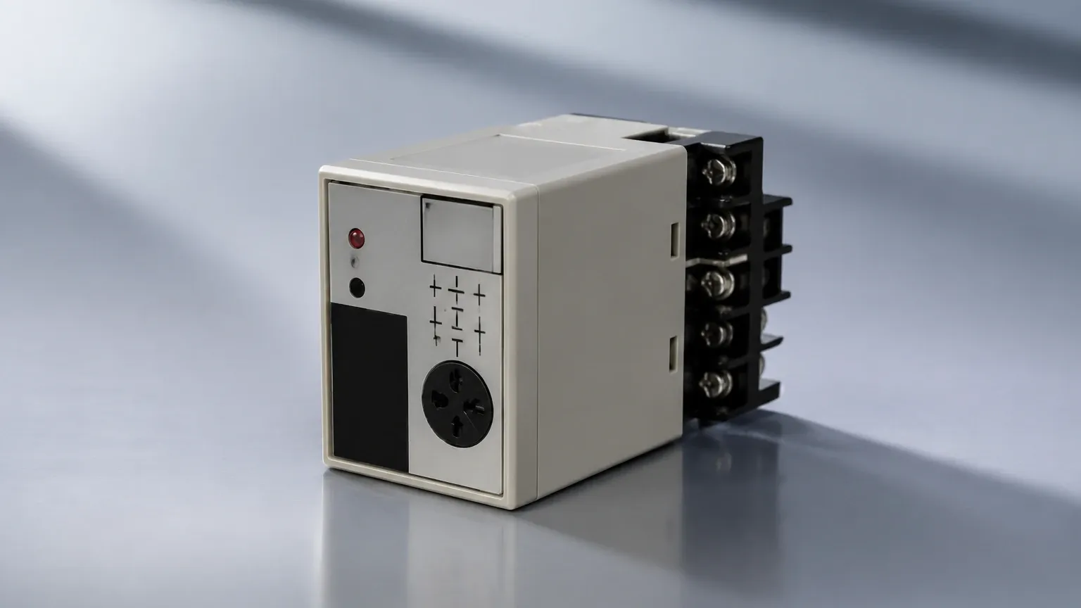
The floatless level switch 61f gp n omron is a plug-in type controller designed for ease of maintenance and compact installation. It is frequently housed in a 11-pin round socket (PF113A), making it easy to replace without rewiring the entire panel.
| Feature | Specification |
| :— | :— |
| Supply Voltage | 100, 110, 120, 200, 220, or 240 VAC; 50/60 Hz |
| Inter-electrode Voltage | 8 VAC |
| Power Consumption | Approx. 3.5 VA maximum |
| Response Time | Operate: 80 ms max; Release: 160 ms max |
| Control Output | 5 A at 250 VAC (Resistive load) |
| Ambient Temperature | -10°C to 55°C |
| Ambient Humidity | 45% to 85% RH |
| Insulation Resistance | 100 MΩ min. (at 500 VDC) |
Sensitivity Variants
Not all liquids have the same conductivity. Therefore, the 61F-GP-N is available in different sensitivity models:
* Standard Type: For general water and sewage (0 to 4 kΩ).
* High-Sensitivity Type (H): For liquids with low conductivity, such as distilled water or high-temperature liquids (up to 70 kΩ).
* Low-Sensitivity Type (L): For liquids with extremely high conductivity or where foaming might cause false triggers (0 to 0.8 kΩ).
* Long-Distance Type (R): Designed for applications where the controller is located far from the electrodes (up to 4 km wiring distance).
Selection Criteria and Application Suitability
When evaluating the floatless level switch 61f gp n omron against other Level Switches, engineers must consider the chemical and physical properties of the medium.
Suitable Media
Conductive switches are ideal for:
* Tap water and well water.
* Sewage and wastewater (with appropriate electrode cleaning).
* Liquid fertilizers and aqueous chemical solutions.
* Boiler water (using high-temperature electrode holders).
Unsuitable Media
Because the technology relies on electrical current flow, it cannot be used with non-conductive liquids. This includes:
* Oils (mineral, vegetable, or synthetic).
* Pure water or deionized water (unless using the ultra-high sensitivity model).
* Liquids with high concentrations of solid matter that may coat the electrodes in an insulating layer.
* Highly flammable liquids where even a low-voltage spark could pose a risk (unless used with an intrinsic safety barrier).
Installation and Wiring Guidelines
Proper installation is paramount to ensuring the longevity and accuracy of the 61F-GP-N system. The following engineering considerations should be followed:
Electrode Selection and Assembly
The electrodes are typically stainless steel (SUS304 or SUS316) rods, often 1 meter in length, which can be connected using coupling nuts to reach greater depths. For corrosive environments, titanium or Hastelloy electrodes may be required.
1. Electrode Holders: Use a dedicated holder (like the PS-3S) to secure the rods and ensure they do not touch each other or the tank walls.
2. Separators: If the rods exceed 1 meter in length, ceramic or plastic separators should be used every 800 mm to 1000 mm to prevent the rods from swaying and touching, which would cause a short circuit.
3. Drip Covers: In outdoor installations or areas with high condensation, use a protective cover over the electrode holder to prevent moisture from bridging the terminals.
Wiring Considerations
* Shielding: For long-distance wiring, use shielded cable to prevent electromagnetic interference (EMI) from nearby power lines, which could induce a voltage in the electrode lines and cause false tripping.
* Grounding: Ensure the E3 (common) electrode is properly grounded. If the tank is metal, the tank wall itself can sometimes serve as the common electrode, though a dedicated rod is always preferred for reliability.
* Socket Orientation: When using the PF113A socket, ensure there is sufficient clearance for the 61F-GP-N unit to be plugged in and secured with the hold-down clips.
Operational Limitations and Common Risks
While the floatless level switch 61f gp n omron is a robust industrial component, it is not immune to environmental challenges. Understanding these risks allows for better system design.
1. Turbulence and Surface Ripples
If the liquid surface is highly turbulent (e.g., near an inlet pipe), the electrodes may experience rapid contact and loss of contact. While the self-holding circuit (E1-E2) mitigates this, extreme turbulence can still lead to relay wear. In such cases, installing a stilling well (a perforated pipe around the electrodes) is recommended.
2. Electrode Fouling and Scaling
In wastewater or hard water applications, calcium deposits or organic film can build up on the electrode rods. This buildup increases the resistance between the electrodes. If the resistance exceeds the sensitivity threshold of the controller, the switch will fail to detect the liquid. Regular inspection and cleaning of the rods are necessary in these environments.
3. Humidity and Condensation
High humidity inside the electrode holder can create a conductive path between the terminals of E1, E2, and E3. This "phantom" conductivity can make the controller think the tank is full when it is actually empty. Using high-quality insulators and ensuring the holder is well-sealed is vital.
4. Lightning and Surges
Because the electrodes are essentially long conductors reaching into a tank, they can act as antennas for atmospheric surges. In regions prone to lightning, surge suppressors should be installed on the electrode lines to protect the 61F-GP-N internal circuitry.
Maintenance and Troubleshooting
Maintenance for a conductive level system is generally low, but a periodic schedule should be established.
* Monthly Check: Visually inspect the controller's LED indicators. Most 61F-GP-N units have an operation indicator that lights up when the relay is energized.
* Quarterly Check: Measure the resistance between the electrodes when the tank is full. If the resistance is creeping upward, it indicates scaling on the rods.
* Annual Check: Verify the integrity of the electrode separators and the tightness of the wiring terminals in the socket.
Troubleshooting Table:
| Symptom | Possible Cause | Solution |
| :— | :— | :— |
| Pump won't start | Broken wire to E2 or E3; sensitivity too low. | Check wiring continuity; switch to high-sensitivity model. |
| Pump won't stop | Scale buildup on E1; E1 and E3 shorted by debris. | Clean electrode rods; remove debris from holder. |
| Relay chatters | Turbulence at surface; E2 rod too short. | Install stilling well; check electrode lengths. |
| False trigger (empty tank) | Condensation in holder; moisture in conduit. | Dry out holder; improve sealing and drainage. |
Frequently Asked Questions
Q: Can I use the 61F-GP-N for oil level detection?
No. Oils are non-conductive. For oil applications, you should consider float-type Level Switches, ultrasonic sensors, or capacitive level switches.
Q: What is the maximum length the electrodes can be?
Technically, electrodes can be several meters long using couplings. However, for lengths over 5 meters, the weight of the rods and the potential for swaying make other technologies, like hydrostatic pressure transmitters, more practical and cost-effective.
Q: Can I cut the electrode rods to size?
Yes, stainless steel electrode rods can be cut to the specific lengths required for your tank's high and low setpoints. Ensure you deburr the cut ends to prevent snagging on debris.
Q: Is the 61F-GP-N compatible with 24V DC power?
The standard 61F-GP-N is an AC-powered device. If your system only provides 24V DC, you would need a different model within the Omron lineup or a DC-to-AC inverter, though it is usually better to select a native DC level controller.
Q: How does the 61F-GP-N handle foam?
Standard conductive switches may struggle with thick foam, as the foam can be conductive enough to trigger the sensor even after the liquid level has dropped. In high-foam applications, a low-sensitivity model (61F-GP-NL) is often used to ensure the relay only triggers when in contact with the bulk liquid.
By carefully matching the model sensitivity to the liquid properties and following rigorous installation standards, the floatless level switch 61f gp n omron provides a reliable, long-term solution for industrial level control. For applications involving non-conductive media or requiring continuous level data, exploring the broader range of industrial Level Switches and transmitters is recommended to ensure optimal process performance.