Two Level Switches
Two Level Switches
In industrial process control, the use of two level switches is a fundamental architectural requirement for managing vessel filling, emptying, and safety interlocking. While a single point level sensor can indicate whether a material has reached a specific height, a dual-switch configuration allows for automated control logic, such as hysteresis-based pump management and redundant overfill protection. Selecting the correct technology for these switches requires a deep understanding of the media properties, vessel environment, and the specific measurement principles involved.
Understanding the Role of Two Level Switches in Process Automation
When engineers specify two level switches for a tank or silo, they are typically addressing one of two primary functional requirements: differential control or safety redundancy.
Differential Level Control (Pump Logic)
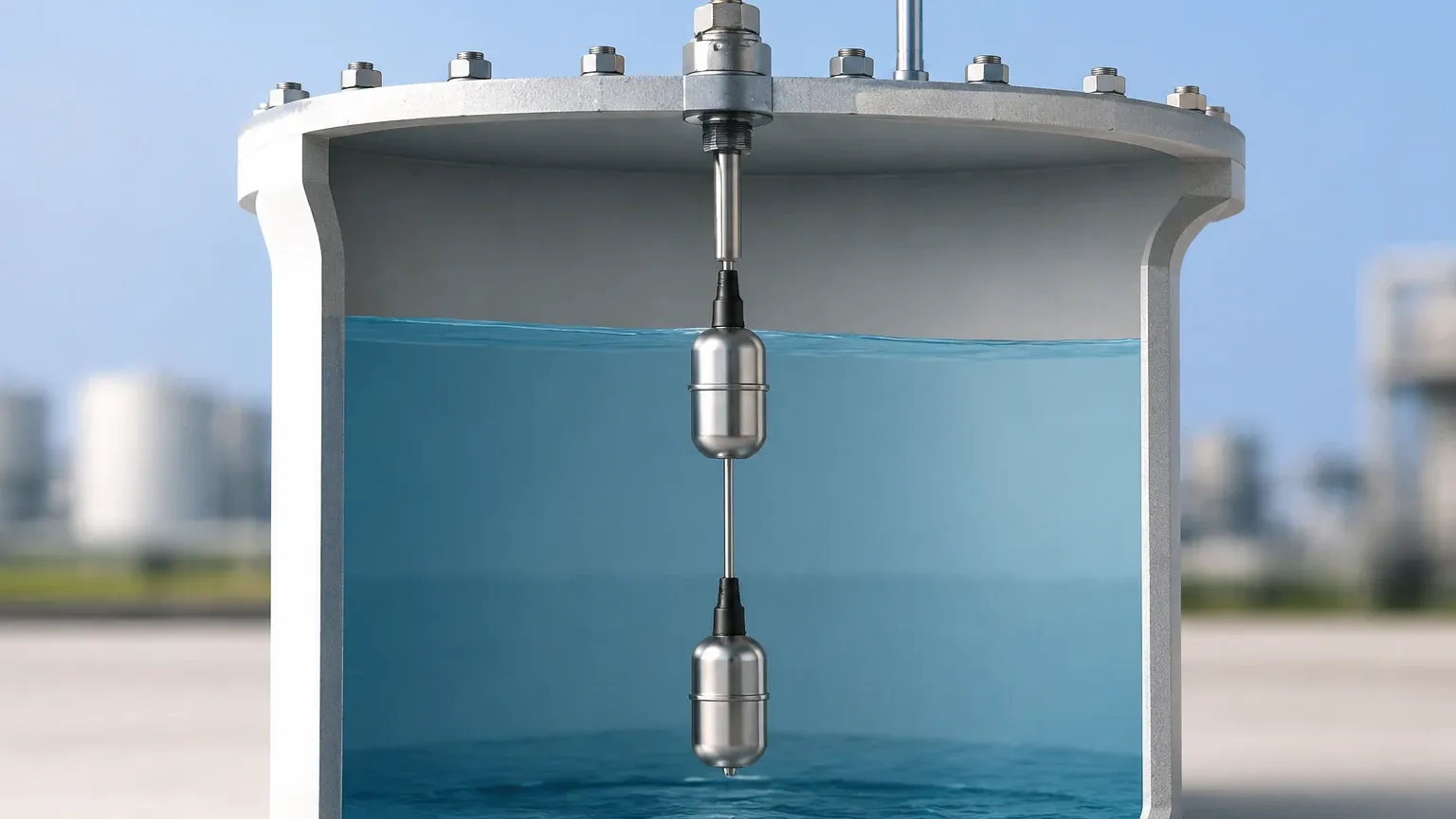
In most liquid handling applications, a single switch would cause a pump to "chatter"—rapidly cycling on and off as the liquid surface ripples at the setpoint. By employing two level switches, a control system can establish a "deadband" or hysteresis zone. For example, in a sump pump application, the lower switch acts as the "Pump Off" trigger, while the upper switch acts as the "Pump On" trigger. This prevents unnecessary wear on mechanical components and ensures stable process flow.
High-High and Low-Low Alarms
In safety-critical environments, such as chemical processing or oil and gas storage, two level switches are often used to provide layered protection. The first switch serves as a standard high-level alarm to alert operators to stop a process. The second switch, positioned slightly higher (High-High), acts as an emergency interlock that can physically cut power to an inlet valve or pump to prevent a catastrophic overflow. This configuration is essential for compliance with safety integrity level (SIL) standards.
Core Measurement Principles for Point Level Detection
Before selecting hardware, it is essential to understand how different Level Switches interact with the process media. Each principle has distinct advantages depending on the physical state of the material (liquid vs. solid) and the environmental conditions.
1. Vibrating Tuning Fork Switches
The vibrating or "tuning fork" switch operates by maintaining a specific resonant frequency in the air. When the media (liquid or fine-grained solid) covers the tines, the frequency drops or the vibration is dampened. An internal electronic circuit detects this change and toggles the output relay. These are highly reliable because they are largely unaffected by flow, turbulence, bubbles, or foam.
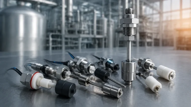
2. Float Level Switches
Float switches rely on buoyancy. A magnetic float moves with the liquid level along a stem, triggering a reed switch located inside the shaft. While mechanically simple and cost-effective, they are susceptible to jamming if the liquid contains high levels of particulates or if the media is highly viscous (e.g., heavy oils or slurries).
3. Capacitance Level Switches
Capacitance switches measure the change in electrical capacitance between the sensor probe and the vessel wall (or a reference electrode). As the media displaces air around the probe, the dielectric constant changes. This technology is excellent for detecting the interface between two different liquids (like oil and water) but requires calibration based on the specific dielectric properties of the media.
4. Ultrasonic Level Switches
Ultrasonic point switches utilize a gap between two piezoelectric crystals. When the gap is filled with liquid, ultrasonic waves travel across it; when the gap contains air, the signal is attenuated. These are non-contact in terms of moving parts and are ideal for corrosive liquids where mechanical components might fail.
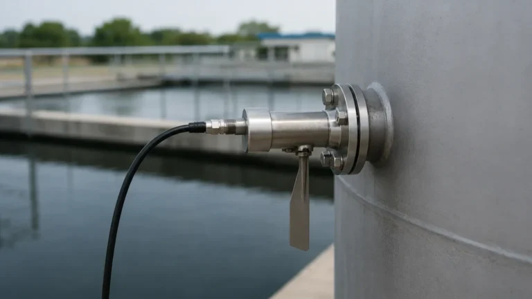
5. Rotary Paddle Switches
Designed specifically for bulk solids and powders, these switches use a low-speed motor to rotate a paddle. When the material reaches the paddle, it creates mechanical resistance, causing the motor to pivot and trigger a switch. These are the standard choice for grain silos, cement hoppers, and plastic pellet bins.
Practical Selection Criteria for Industrial Applications
Choosing the right pair of switches involves evaluating the physical and chemical constraints of the application. The following table provides a comparative overview of common technologies used when implementing two level switches.
| Technology | Media Type | Temp. Range | Pressure Range | Best For |
| :— | :— | :— | :— | :— |
| Vibrating Fork | Liquids/Solids | -50°C to 150°C | Up to 40 Bar | General purpose, foam-resistant |
| Float | Clean Liquids | -10°C to 120°C | Up to 20 Bar | Simple pump control, low cost |
| Capacitance | Liquids/Pastes | -40°C to 200°C | Up to 100 Bar | High pressure, interface detection |
| Rotary Paddle | Bulk Solids | -20°C to 80°C | Atmospheric | Silos, powders, aggregates |
| Ultrasonic Gap | Liquids | -40°C to 100°C | Up to 10 Bar | Corrosive chemicals, no moving parts |
Media Characteristics
* Viscosity: High-viscosity liquids can cause "bridging" on tuning forks or stickiness on floats. In these cases, capacitance or flush-mounted sensors are preferred.
* Conductivity: Some sensors require the media to be conductive to complete a circuit, though this is less common in modern universal switches.
* Corrosivity: For aggressive acids or bases, wetted parts must be constructed from materials like PTFE, PVDF, or high-grade Stainless Steel (316L).
Installation Best Practices for Dual Switch Configurations
Proper installation is critical to ensure that the two level switches function correctly over the long term. Failure to account for vessel dynamics can lead to false triggers or mechanical failure.
Positioning and Orientation
When installing two switches for high/low control, ensure there is sufficient vertical distance between them to prevent rapid cycling. In tall, narrow tanks, switches are typically mounted horizontally through the side wall. In shallow basins, they may be suspended from the top using cable-extension versions.
Avoiding Turbulence and Inflow
Switches should never be placed directly in the path of an incoming material stream. The force of falling liquid or solids can cause mechanical damage to paddles or floats and lead to erratic signaling. If side-mounting is the only option near an inlet, a baffle plate should be installed to shield the sensor.
Wiring and Fail-Safe Logic
When configuring the electrical output, engineers must choose between Normally Open (NO) and Normally Closed (NC) configurations. For safety applications (High-High alarm), a "Fail-Safe High" logic is recommended. This means the switch is energized when the level is low and de-energizes when the level is high or if power is lost, ensuring the system defaults to a safe state during a failure.
Operational Limitations and Environmental Factors
While robust, all point level technologies have limitations that must be managed during the design phase:
1. Build-up and Coating: In applications involving sticky resins or wastewater, material can accumulate on the sensor. Vibrating forks are somewhat self-cleaning due to their motion, but heavy build-up will eventually dampen the vibration and cause a false "full" signal.
2. Vibration and Shock: In heavy industrial environments, external vessel vibration can interfere with the resonance of tuning fork switches. Using dampened mounts or switching to a capacitance-based sensor can mitigate this.
3. Foam and Aeration: Many sensors struggle to distinguish between a dense foam layer and the actual liquid level. If foam is present, ultrasonic gap switches or specific tuning forks tuned for higher densities are required to avoid premature switching.
4. Dielectric Changes: For capacitance switches, if the moisture content of a solid or the composition of a liquid changes significantly, the switch may require recalibration to maintain accuracy.
Frequently Asked Questions (FAQs)
Q: Can I use one switch with two setpoints instead of two level switches?
A: Some specialized technologies, like continuous radar or ultrasonic transmitters, can provide multiple virtual switch points via software. However, for hardware-level safety and simple pump control, using two discrete physical switches is often preferred for reliability and ease of wiring into motor starters.
Q: How do I handle two level switches in a hazardous (Ex) zone?
A: You must select switches with appropriate certifications (e.g., ATEX, IECEx). These typically use intrinsically safe (IS) circuits or explosion-proof housings to prevent electrical sparks from igniting the surrounding atmosphere.
Q: What is the maintenance schedule for these switches?
A: For clean liquids, an annual visual inspection and functional test (tripping the switch manually or by raising the level) is usually sufficient. In fouling or corrosive applications, quarterly cleaning may be necessary to prevent material build-up from affecting the measurement principle.
Q: Can two level switches be used for solids and liquids in the same tank?
A: Yes, but the technology must be compatible with both. A vibrating fork switch is one of the few technologies capable of detecting both liquid levels and solid sediment levels at the bottom of a tank, making it a versatile choice for complex separation processes.
Conclusion
Implementing a system with two level switches is a proven method for achieving reliable process automation and safety. By selecting the measurement principle that best aligns with the media properties—whether it be the mechanical simplicity of a float, the versatility of a tuning fork, or the robustness of a rotary paddle—facilities can minimize downtime and prevent environmental hazards. Always consult the technical specifications of your specific Level Switches to ensure compatibility with the operating temperature, pressure, and chemical environment of your application.