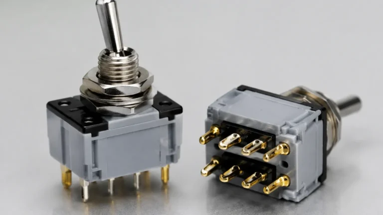
Level Switch L 471 11
Level Switch L 471 11
In the landscape of industrial process control, point-level detection remains a critical safety and operational requirement. Among the various technologies available, the magnetic float-operated level switch is a cornerstone for high-pressure and high-temperature liquid applications. The level switch l 471 11 represents a specific configuration of this technology, engineered for horizontal mounting and reliable performance in demanding environments such as oil and gas, chemical processing, and power generation. This guide examines the technical foundations, selection criteria, and installation best practices for Level Switches within this category.
Understanding the Measurement Principle
Before selecting a specific model like the level switch l 471 11, it is essential to understand the physics of its operation. These devices operate on the principle of buoyancy and magnetic coupling, which ensures that the electrical components remain completely isolated from the process media.
The Buoyancy Effect
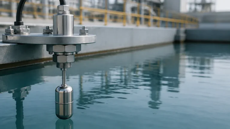
A float, typically constructed from 316 stainless steel or specialized alloys, is designed with a density lower than the process liquid. As the liquid level rises within a tank or vessel, the float moves upward. In a horizontal configuration, the float is attached to a rod that pivots at a fixed point.
Magnetic Coupling and Snap-Action
The critical innovation in the L 471 series is the use of magnetic repulsion or attraction to actuate the switch. A permanent magnet is attached to the end of the float rod inside the process-wetted area. On the other side of a non-magnetic pressure wall (the switch housing), a second magnet is linked to a micro-switch or a mercury-free contact set.
As the float rises, the internal magnet moves closer to the external magnet. The magnetic field passes through the solid metal wall, causing the external magnet to move and trigger the switch. This "snap-action" design prevents "chattering"—a common issue where a switch rapidly toggles on and off due to surface turbulence or vibration. Because there is no physical mechanical link (like a seal or bellows) between the float and the switch, the risk of leaks is virtually eliminated.
Technical Specifications of the Level Switch L 471 11
The "L 471 11" designation typically refers to a specific build of a heavy-duty magnetic float switch. While exact specifications can vary by manufacturer, the following parameters are characteristic of this industrial-grade equipment:
* Mounting Type: Horizontal, flanged connection (commonly 92mm or 3.5-inch square flanges).
* Wetted Materials: 316L Stainless Steel as standard; exotic alloys available for corrosive media.
* Pressure Rating: Capable of operating in high-pressure environments up to 18.5 MPa (185 bar) or higher depending on the flange rating.
* Temperature Range: Standard models handle -50°C to +250°C (-58°F to 482°F), with high-temperature variants reaching up to 400°C (752°F).
* Specific Gravity (Density): Typically requires a minimum liquid density of 0.5 g/cm³ (500 kg/m³) to ensure sufficient buoyant force.
Selection Criteria and Technology Comparison
Choosing the correct level switch requires an evaluation of the process media and the physical constraints of the vessel. The following table compares the magnetic float technology used in the level switch l 471 11 with other common point-level detection methods.
Table 1: Level Detection Technology Comparison
| Feature | Magnetic Float (L 471 11) | Vibrating Tuning Fork | Ultrasonic Gap Switch |
| :— | :— | :— | :— |
| Measurement Type | Mechanical/Magnetic | Electronic Frequency | Acoustic Wave |
| Process Temperature | Very High (Up to 400°C) | Moderate (Up to 150°C) | Low to Moderate |
| Process Pressure | Very High (Up to 200 bar) | High (Up to 64 bar) | Moderate |
| Viscosity Limit | Moderate (Up to 2000 cP) | High (Up to 10,000 cP) | Low (Clean liquids only) |
| Coating/Buildup | Sensitive to heavy scaling | Resistant | Very Sensitive |
| Power Required | None (Passive contact) | Required (Loop or AC) | Required |
When to Choose the L 471 11
This model is preferred when the application involves high-pressure steam, boiler water level control, or hazardous chemicals where a power-free, fail-safe mechanical switch is required for emergency shutdown (ESD) systems.
Installation Considerations
Proper installation is paramount to the longevity and accuracy of the level switch l 471 11. Engineers should adhere to the following guidelines during the design and commissioning phases:
1. Orientation and Clearance: The switch must be mounted horizontally. Ensure there is sufficient internal clearance for the float's arc of travel. If the vessel has internal baffles or heating coils, these must not interfere with the float.
2. Nozzle Length: The nozzle (the pipe section extending from the tank to the flange) must be short enough to allow the float to move freely. If the nozzle is too long, the float rod may hit the top or bottom of the pipe before the switch actuates.
3. Turbulence and Stillwells: In tanks with high agitation or surface turbulence, the float may bounce, leading to premature wear. In such cases, installing the switch inside a stillwell (a perforated pipe) or a side-mounted chamber is recommended.
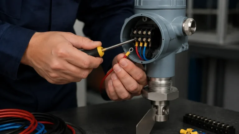
4. Wiring and Conduit: Use appropriate cable glands to maintain the IP rating of the switch housing. For hazardous areas, ensure the enclosure is certified (ATEX/IECEx) and that the wiring follows local explosion-proof standards.
Limitations and Operational Risks
While robust, the level switch l 471 11 is not a universal solution. Engineers must be aware of the following limitations:
* Mechanical Wear: Because it has moving parts, the pivot pin and float rod are subject to mechanical wear over decades of use. Regular inspection is required in high-cycle applications.
* Particulate Accumulation: If the liquid contains magnetic particles (e.g., iron filings), they may adhere to the internal magnet, potentially jamming the mechanism. Similarly, heavy scaling or crystallization can weigh down the float.
* Density Fluctuations: If the process liquid density drops below the float's design limit (e.g., during a temperature spike), the float may fail to rise, resulting in a non-trip condition.
Maintenance and Troubleshooting
To ensure the reliability of Level Switches in safety-critical roles, a preventative maintenance schedule should be established.
Functional Testing (Proof Testing)
Most L 471 11 models feature a manual check lever or a test magnet. This allows operators to manually actuate the switch from the outside without changing the liquid level in the tank. This is a vital feature for verifying the integrity of the alarm circuit or pump control logic.
Common Issues and Solutions
* Switch fails to reset: Check for debris or buildup around the pivot point. Ensure the float hasn't been crushed by a pressure surge (implosion).
* Intermittent signals: Inspect the wiring terminals for corrosion or loose connections. Vibration may also cause the internal micro-switch to wear out prematurely.
* Leakage into housing: While rare due to the magnetic coupling, if the pressure-retaining wall is breached (due to extreme corrosion), liquid may enter the switch head. This requires immediate replacement of the unit.
Frequently Asked Questions (FAQ)
Q: Can the level switch l 471 11 be used for interface detection?
A: Yes, provided the float is weighted specifically for the interface. The float must be heavy enough to sink through the upper (lighter) liquid but buoyant enough to float on the lower (heavier) liquid. A minimum density difference of 0.1 g/cm³ is typically required.
Q: Is this switch suitable for hygienic applications in the food industry?
A: Generally, no. The pivot mechanism and the internal mounting of the float create "dead zones" where bacteria can grow. For hygienic applications, a tuning fork or a flush-mounted hydrostatic transmitter is usually preferred.
Q: What is the difference between a SPDT and DPDT contact in these switches?
A: SPDT (Single Pole Double Throw) provides one set of contacts (Common, Normally Open, Normally Closed). DPDT (Double Pole Double Throw) provides two independent sets, allowing you to trigger two separate circuits (e.g., a local alarm and a remote PLC input) simultaneously.
Conclusion
The level switch l 471 11 remains a gold standard for point-level detection in high-stakes industrial environments. Its reliance on fundamental physical principles—buoyancy and magnetism—makes it an exceptionally reliable component for overfill protection and pump control. By understanding the specific requirements for liquid density, pressure, and installation geometry, plant engineers can ensure that these devices provide decades of maintenance-free service. For those exploring modern alternatives or specific configurations, Welk offers a comprehensive range of Level Switches tailored to diverse industrial needs.