8 Light Switches
8 Light Switches
In industrial automation and process control, the term "8 light switches" often refers to the visual interface of a multi-channel level monitoring system. While a single-point sensor provides a basic binary signal, complex industrial environments—such as tank farms, chemical processing plants, and water treatment facilities—frequently require the simultaneous monitoring of multiple points. An 8-channel annunciator or control panel, featuring 8 indicator lights, serves as the central hub for Level Switches distributed across various vessels or at different heights within a single large silo.
Understanding how these switches function, how they interface with indicator panels, and how to select the right technology is critical for ensuring operational safety and preventing costly overflows or dry-run conditions.
Measurement Principles of Level Switches
Before configuring a system with 8 light switches on a control panel, it is essential to understand the physical principles that trigger these signals. Level switches are "point level" sensors, meaning they detect the presence or absence of a material at a specific height. Unlike continuous level transmitters, they do not provide a percentage of volume; they provide an On/Off state.
1. Float Level Switches (Buoyancy Principle)
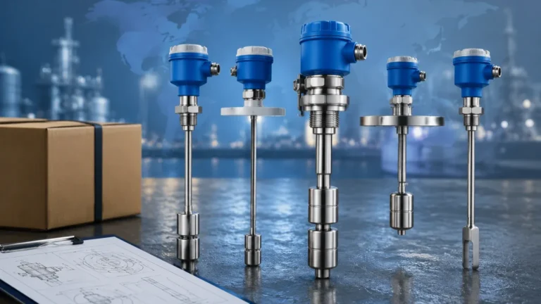
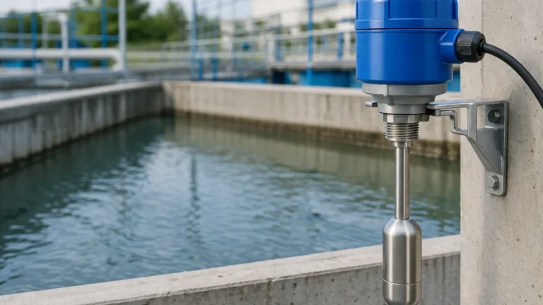
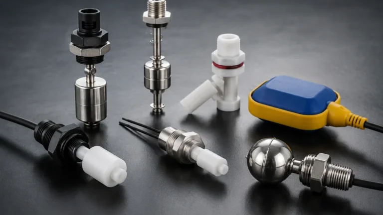
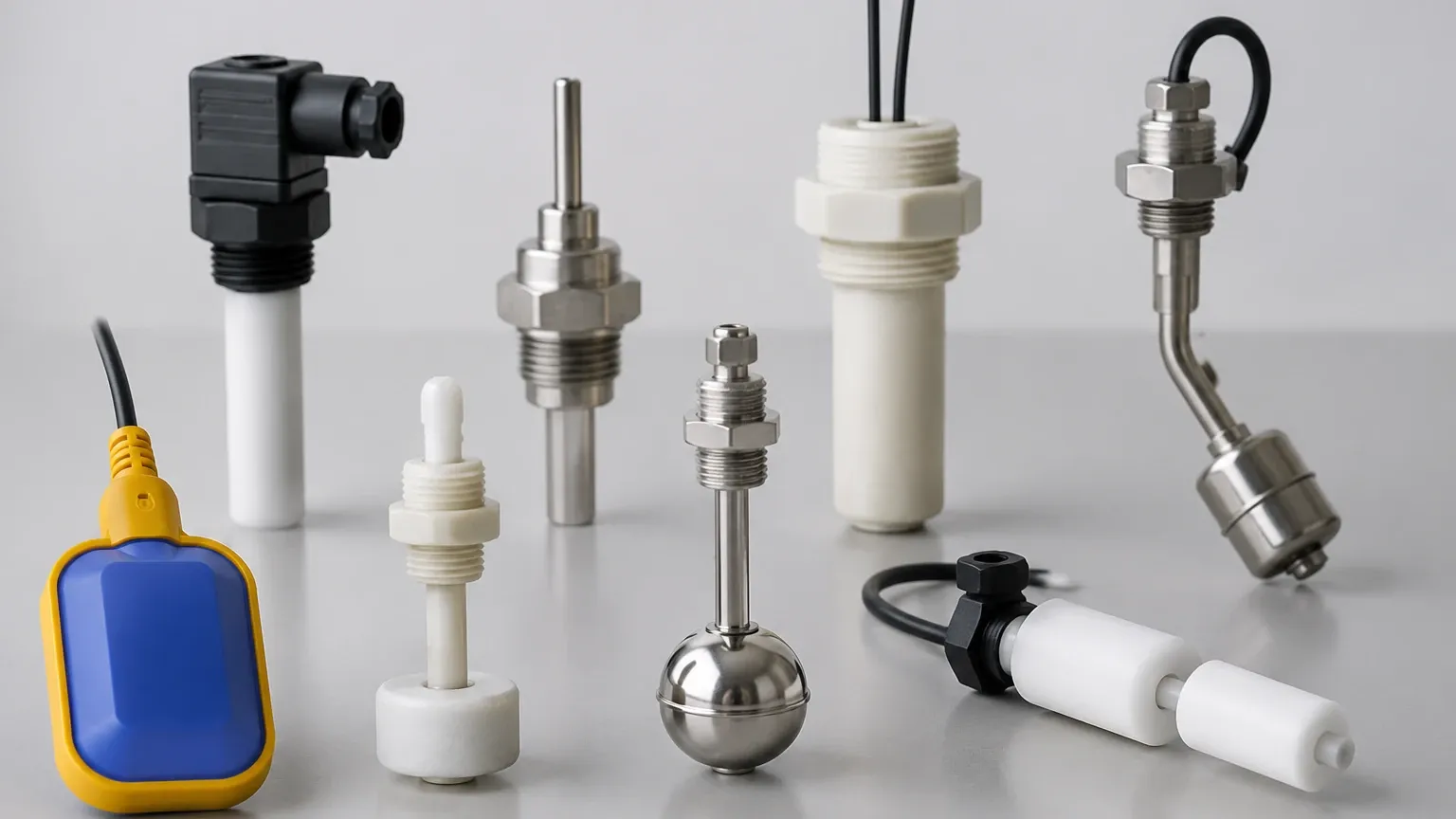
Float switches utilize a magnetic float that rises and falls with the liquid level. As the float moves, it actuates a reed switch or a microswitch. In a multi-point setup, several floats can be mounted on a single stem, or eight individual switches can be wired to an 8-light monitoring panel. This technology is reliable for clean liquids but can struggle with viscous or coating-heavy media.
2. Tuning Fork (Vibration Principle)
Tuning fork switches, or vibrating level switches, use a piezoelectric crystal to vibrate a fork at its natural frequency. When the fork is immersed in a liquid or solid, the frequency changes. The electronics detect this shift and trigger the switch. These are excellent for high-pressure environments (up to 40 bar or more) and are unaffected by turbulence or bubbles.
3. Capacitive Level Switches
These sensors measure the change in capacitance between the probe and the tank wall (or a reference electrode). When the material covers the probe, the dielectric constant changes, triggering the output. They are versatile but require calibration based on the specific dielectric properties of the medium.
4. Optoelectronic Level Switches
Optical switches use an infrared LED and a light receiver. When the sensor tip is in air, the light is reflected back to the receiver. When immersed in liquid, the light is refracted into the liquid, and the receiver detects a loss of signal. This is a common technology for compact systems where 8 light switches might be used to monitor small laboratory or pharmaceutical containers.
Integrating 8 Light Switches into Control Systems
When an engineer specifies a system requiring 8 light switches, they are typically designing a localized monitoring station. This setup is common in the following scenarios:
* Tank Farm Monitoring: Monitoring the "High Level" alarm for 8 separate storage tanks.
* Multi-Stage Filtration: Tracking the status of 8 different filter banks to determine when backwashing is required.
* Sump Pump Arrays: Controlling a series of pumps where 8 different levels (Low-Low, Low, High, High-High across multiple pits) are indicated by a central 8-light panel.
In these configurations, the level switches are wired to a digital input module of a PLC or a dedicated annunciator. The "8 lights" provide immediate visual feedback to operators on the factory floor, allowing for rapid response without needing to consult a complex HMI (Human Machine Interface) screen.
Selection Criteria for Multi-Point Systems
Choosing the correct hardware for an 8-point monitoring system requires a detailed analysis of the process conditions. The following table provides a comparison of common technologies used in industrial applications.
Level Switch Technology Comparison
| Technology | Suitable Media | Max Pressure (Typical) | Max Temperature | Advantages |
| :— | :— | :— | :— | :— |
| Float | Clean Liquids | 20 bar (2.0 MPa) | 150°C | Low cost, no power required for reed types |
| Tuning Fork | Liquids & Solids | 40 bar (4.0 MPa) | 250°C | High reliability, no calibration needed |
| Capacitive | Powders, Liquids | 25 bar (2.5 MPa) | 200°C | No moving parts, adjustable sensitivity |
| Optical | Clear Liquids | 50 bar (5.0 MPa) | 125°C | Extremely compact, fast response |
| Hydrostatic | Liquids | N/A (Submersible) | 80°C | Good for deep wells or sumps |
Installation and Configuration Guidelines
To ensure that the 8 light switches on your panel accurately reflect the state of your process, follow these installation best practices:
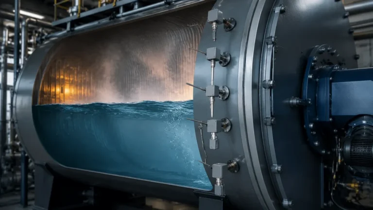
1. Avoid Turbulence: Do not install level switches directly in the path of an incoming fluid stream. The force of the fluid can cause false triggers or mechanical damage. Use a stilling well if turbulence is unavoidable.
2. Mounting Orientation: Some switches, like tuning forks, should be mounted at a slight downward angle (approx. 20°) if used in viscous liquids to allow the medium to drip off the blades easily.
3. Wiring and Grounding: For a system involving 8 separate signals, use shielded cables to prevent electromagnetic interference (EMI) from nearby motors or VFDs. Ensure the control panel is properly grounded to avoid "ghost" signals on the indicator lights.
4. Dead Band Consideration: Understand the "hysteresis" or dead band of the switch. This is the distance between the point where the switch turns on and the point where it turns off. For 8-light systems controlling pumps, a wider dead band prevents the lights from flickering and the pumps from "hunting."
Limitations and Operational Risks
While an 8-light level switch system is a robust solution, engineers must be aware of specific limitations:
* Coating and Buildup: In applications involving wastewater or cement, material can build up on the sensor. This may cause a "stuck" signal, where the light remains on even after the level has dropped. Tuning fork and capacitive switches with "active shield" technology are better suited for these environments.
* Media Density: Float switches are dependent on the density (specific gravity) of the liquid. If the process fluid changes from water (SG 1.0) to an oil (SG 0.8), the float may no longer trigger at the correct height.
* Mechanical Wear: Any switch with moving parts, such as a float or a rotating paddle, is subject to mechanical fatigue over time. In critical safety applications (SIL-rated), non-mechanical switches like tuning forks are preferred.
Frequently Asked Questions (FAQ)
Q: Can I use 8 light switches to monitor both liquids and solids in the same panel?
A: Yes. The indicator panel only cares about the electrical signal (usually a dry contact or a 24V DC signal). You can mix tuning fork switches for solids and float switches for liquids, feeding all signals into the same 8-channel display.
Q: What is the maximum distance between the level switches and the indicator lights?
A: This depends on the signal type. For standard relay contacts or 24V DC signals, distances of 100 to 300 meters are common. For longer distances, you may need to use a 4-20mA signal or a digital communication protocol like Modbus to avoid voltage drop.
Q: How do I test if the 8 lights are working correctly?
A: Most industrial annunciator panels include a "Lamp Test" button. Pressing this should illuminate all 8 lights simultaneously to ensure no bulbs or LEDs are burned out. To test the switches themselves, you must manually actuate them or raise the level of the media during a maintenance cycle.
Q: Are these systems suitable for hazardous areas?
A: Yes, but you must use intrinsically safe (IS) barriers or explosion-proof housings for the switches located in the hazardous zone. The control panel with the 8 lights is typically located in a safe area, such as a control room or a non-hazardous electrical shed.
Conclusion
Implementing a system of 8 light switches for level monitoring provides a clear, effective way to manage multiple process points. By selecting the appropriate measurement principle—whether it be the ruggedness of a tuning fork or the simplicity of a float—and adhering to strict installation guidelines, industrial operators can maintain high safety standards and process efficiency. Always confirm the chemical compatibility of the switch wetted parts with your process media before installation to ensure a long service life.