Level Switch for Sump Pump
Level Switch for Sump Pump
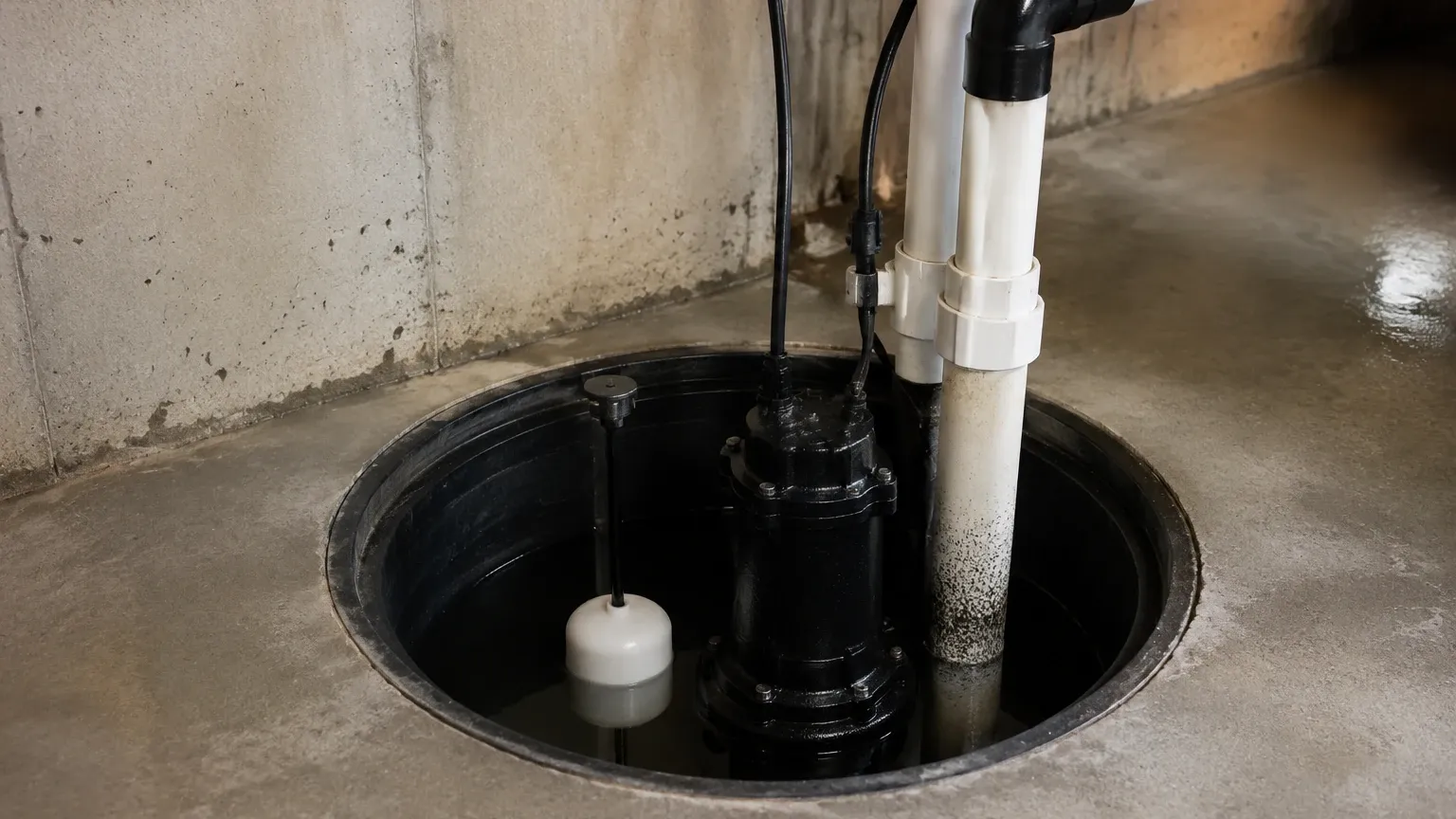
In industrial and commercial water management, the sump pump is a critical component for preventing flooding, managing wastewater, and ensuring the integrity of sub-grade structures. However, a pump is only as reliable as the control mechanism that triggers it. The level switch for sump pump applications serves as the primary interface between the physical fluid level and the electrical drive of the pump motor. Selecting the correct technology is not merely a matter of convenience; it is a fundamental engineering decision that impacts system longevity, maintenance costs, and operational safety.
Industrial sumps often deal with more than just clean groundwater. They may contain corrosive chemicals, suspended solids, oils, or varying temperatures. Consequently, a standard consumer-grade float is rarely sufficient. This guide explores the measurement principles, selection criteria, and installation nuances required to implement robust Level Switches in professional sump pump environments.
Understanding the Role of Level Switches in Sump Pump Systems
A level switch serves two primary functions in a sump application: automation and protection. In a basic setup, the switch detects when the liquid has reached a high-level setpoint and closes a circuit to start the pump. Once the level drops to a low-level setpoint, the switch opens the circuit to stop the pump.
Beyond simple automation, these switches provide critical protection against "dry running." If a pump continues to operate after the sump is empty, the lack of fluid for cooling and lubrication can lead to catastrophic seal failure and motor burnout within minutes. Furthermore, high-level alarms—often secondary switches—provide a fail-safe to alert operators or building management systems (BMS) if the primary pump fails to keep up with the inflow.
Core Measurement Principles for Sump Pump Level Control
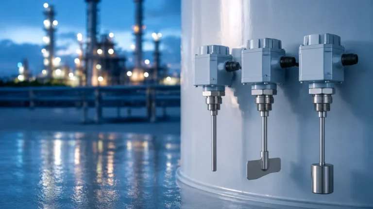
Selecting the right level switch for sump pump duty requires an understanding of how different technologies interact with the fluid. No single technology is universal; the choice depends on the specific characteristics of the sump contents.
Mechanical Float Switches
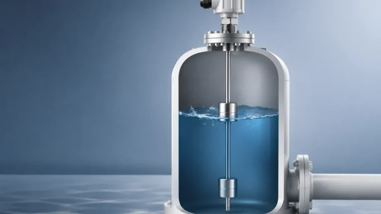
Mechanical floats are the most common technology due to their simplicity and cost-effectiveness. They operate on the principle of buoyancy. As the liquid level rises, a buoyant housing (often containing a microswitch or a rolling ball) tilts or moves vertically.
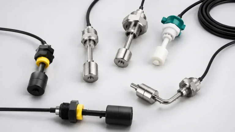
* Tethered Float Switches: These consist of a float attached to a flexible cable. The cable is anchored at a specific depth. As the water rises, the float pivots upward until an internal ball rolls onto a switch. The "tether length" determines the differential (the distance between the turn-on and turn-off points).
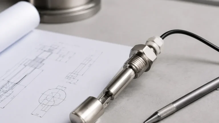
* Vertical Float Switches: These move up and down a rigid shaft. They are ideal for tight sumps where a tethered float might get snagged on the pump or the pit walls. They often use magnetic reeds within the shaft that are triggered by a magnet inside the float.
Diaphragm (Pressure) Switches
Diaphragm switches detect the hydrostatic pressure exerted by the liquid column. As the level in the sump rises, the air pressure inside a trapped chamber or the direct force against a flexible diaphragm increases. Once the pressure reaches a calibrated threshold, the diaphragm flexes and trips a mechanical switch. These are frequently used in applications where surface turbulence or foam might interfere with a floating device.
Conductivity Probes
Conductivity switches use the electrical conductivity of the fluid to complete a circuit. These systems typically employ three probes: a common ground, a low-level probe, and a high-level probe. When the water touches the high-level probe, the circuit is completed, and the pump starts. It continues to run until the level falls below the low-level probe. Because they have no moving parts, they are highly resistant to mechanical wear, though they are unsuitable for non-conductive fluids like pure oils.
Ultrasonic and Non-Contact Sensors
For high-stakes industrial sumps containing aggressive chemicals or heavy sludge, non-contact measurement is preferred. Ultrasonic level switches emit high-frequency sound waves that reflect off the liquid surface. The time-of-flight is measured to determine the level. While more complex, these eliminate the risk of the sensor being fouled or corroded by the media.
Technical Selection Criteria for Industrial Sump Applications
When specifying a level switch for sump pump integration, engineers must evaluate several environmental and electrical factors to ensure long-term reliability.
1. Media Characteristics
The nature of the fluid is the most important factor.
* Viscosity and Solids: If the sump contains sewage or industrial slurry, tethered floats can become coated in "ragging" (debris like wipes or hair), which prevents them from tilting. In these cases, a vertical float or a non-contact ultrasonic sensor is superior.
* Chemical Compatibility: For sumps in chemical processing plants, the switch material (PVC, Polypropylene, or Stainless Steel) must be resistant to the specific acids or bases present.
* Specific Gravity: Mechanical floats are designed for specific fluid densities. If the fluid is significantly lighter than water (e.g., some hydrocarbons), a standard water float may not rise sufficiently to trigger the switch.
2. Sump Dimensions and Geometry
The physical space within the sump pit dictates the form factor of the switch.
* Small Pits: A tethered float requires a wide "swing" radius. If the pit is narrow (e.g., less than 450 mm or 18 inches in diameter), the float may get stuck against the pump housing or the wall, leading to a pump that never turns on (causing a flood) or never turns off (burning out the motor).
* Deep Sumps: For sumps deeper than 3 meters (approx. 10 feet), cable weight and signal attenuation become factors. Heavy-duty weighted cables or hydrostatic pressure transmitters are often preferred over simple floats.
3. Electrical Load and Ratings
It is vital to confirm whether the level switch will directly power the pump or if it will act as a pilot device for a motor starter or relay.
* Direct Control: The switch must be rated for the pump’s horsepower (HP) and full-load amps (FLA).
* Pilot Duty: The switch only carries a small signal current to a control panel. This is the standard for most industrial B2B applications, as it allows for more sophisticated control logic and protects the switch from the high inrush currents of large motors.
Installation Best Practices and Configuration
Correct installation is as important as the hardware itself. Even the highest quality Level Switches will fail if positioned incorrectly.
Setting the Hysteresis (Deadband)
The distance between the "on" and "off" points is known as the differential or deadband. If this distance is too small, the pump will "short cycle," turning on and off every few seconds. Short cycling causes excessive heat in the motor windings and leads to premature failure. For a standard industrial sump, a minimum differential of 150 mm to 300 mm (6 to 12 inches) is usually recommended, depending on the inflow rate.
Avoiding Turbulence
The inflow pipe should not discharge directly onto the level switch. The resulting turbulence can cause the switch to bounce or chatter, sending erratic signals to the pump controller. If the inflow cannot be moved, a "stilling well" (a vertical pipe with small holes that dampens wave action) should be installed around the switch.
Cable Management
In tethered applications, the cable must be secured firmly to a discharge pipe or a dedicated mounting bracket using a non-corrosive clamp. Zip ties are often used but can become brittle over time; stainless steel hose clamps with a rubber grommet are the professional standard. Ensure there is enough slack for the float to move freely but not so much that it can wrap around the pump’s suction intake.
Comparative Analysis of Sump Pump Level Switch Technologies
| Technology | Best For | Pros | Cons |
| :— | :— | :— | :— |
| Tethered Float | Large open sumps, clean water | Low cost, easy to adjust differential | Requires large swing space, prone to snagging |
| Vertical Float | Narrow pits, limited space | Precise switching, small footprint | Can be fouled by debris/grease buildup |
| Conductivity Probes | Wastewater, high-reliability needs | No moving parts, compact | Requires conductive fluid, probes need cleaning |
| Diaphragm Switch | Small sumps with foam | Not affected by surface turbulence | Diaphragm can harden or clog over time |
| Ultrasonic | Corrosive chemicals, slurries | Non-contact, high accuracy | Higher initial cost, requires power supply |
Operational Limitations and Maintenance Requirements
While level switches are designed for durability, they are not "set and forget" devices. In a B2B context, a failure can result in significant downtime or environmental fines.
* Fouling and Buildup: In sumps handling greywater or industrial runoff, fats, oils, and grease (FOG) can accumulate on the switch. This extra weight can prevent a float from rising or create an insulating layer on conductivity probes. Regular cleaning intervals—typically every 3 to 6 months—are necessary.
* Mechanical Fatigue: Every switch has a rated number of cycles (e.g., 100,000 operations). In high-inflow applications where the pump cycles frequently, the internal microswitch or the flexible cable at the pivot point will eventually fail.
* Environmental Limits: Standard PVC cables may become brittle in extremely cold environments or soften in high-temperature industrial discharge (above 60°C or 140°F). Always verify the temperature rating of both the sensor body and the cable jacket.
Frequently Asked Questions (FAQs)
Q: Can I use a single level switch to control two pumps in a duplex system?
A: While a single switch can trigger a control panel, a duplex system typically requires at least three (and often four) switches: Lead Pump Start, Lag Pump Start (for high inflow), and a Common Stop. A fourth switch is usually added for a High-Level Alarm.
Q: How do I test a level switch without filling the sump with water?
A: For mechanical floats, you can manually lift the float to ensure the pump or alarm triggers. For electronic or ultrasonic sensors, most industrial models include a "test" button or allow you to simulate a level via the digital interface. Always ensure the pump is only run for a second or two during dry testing to avoid seal damage.
Q: What is the advantage of a "Normally Open" vs. "Normally Closed" switch in a sump?
A: For pump-down applications (emptying a sump), you need a "Normally Open" (NO) switch. This means the circuit is open (pump off) when the float is down and closes (pump on) when the float rises. Using the wrong configuration will result in the pump running when the tank is empty and stopping when it is full.
Q: Why is my pump humming but not starting when the switch triggers?
A: This is often a sign of a voltage drop or a failing capacitor in the pump, but from a level switch perspective, it could mean the switch contacts are pitted or oxidized, providing some voltage but not enough current to start the motor. This is common when a switch is used at the very limit of its electrical rating.
Conclusion
Selecting the appropriate level switch for sump pump applications is a balance of understanding the chemical environment, the physical constraints of the pit, and the electrical requirements of the motor. By moving beyond basic float switches and considering technologies like conductivity probes or ultrasonic sensors, industrial operators can significantly reduce the risk of flooding and equipment failure. For complex applications, consulting with a professional manufacturer like Welk ensures that the selected Level Switches provide the accuracy and longevity required for demanding industrial automation tasks.