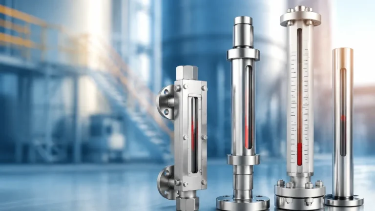
Equipment Level Gauge
Equipment Level Gauge
In industrial process control, the ability to monitor liquid levels accurately and safely is a fundamental requirement. An equipment level gauge serves as a local visual indicator, allowing operators to verify the contents of tanks, pressure vessels, and boilers without relying solely on electronic sensors. While digital automation has advanced significantly, the physical level gauge remains a critical safety and redundancy component in sectors ranging from chemical processing to water treatment.
Selecting the correct equipment level gauge requires a deep understanding of the fluid properties, vessel pressure, and environmental conditions. This guide examines the engineering principles, selection criteria, and installation best practices for various local level indicators, with a specific focus on Magnetic & Local Level Gauges.
Measurement Principles of Level Gauges
Most manual or local level indicators operate on the principle of "communicating vessels." This law of physics states that when two or more containers are connected, the liquid level in each will reach the same height, provided the fluid is at rest and the density is uniform.
The Principle of Communicating Vessels
In a standard bypass or side-mounted equipment level gauge, the gauge chamber is connected to the side of the tank via two process connections (top and bottom). As the liquid level in the main vessel rises or falls, the level in the gauge chamber moves in unison. This allows for a direct or indirect visual representation of the tank's contents.
Magnetic Coupling Principle
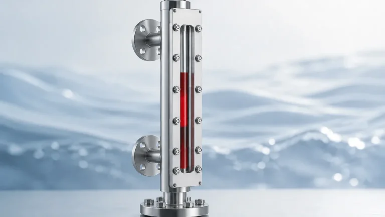
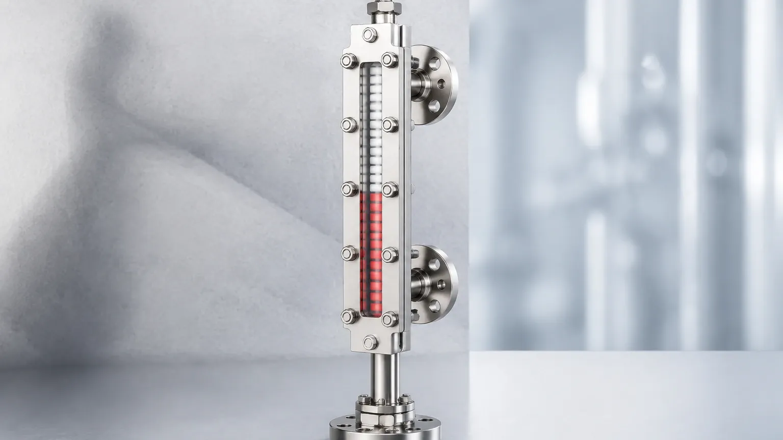
For modern industrial applications, the magnetic level gauge has largely superseded traditional glass gauges due to enhanced safety. This technology utilizes a float containing a high-intensity permanent magnet. As the float rises and falls with the liquid level inside a non-magnetic chamber, its magnetic field penetrates the chamber wall to interact with an external indicator.
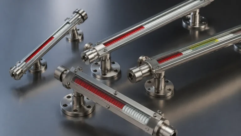
This indicator typically consists of a series of bi-color magnetic flags or rollers. As the float passes, the flags flip 180 degrees, changing color (usually from white to red) to provide a clear, high-contrast visual of the liquid level. Because the liquid is entirely contained within the pressure-sealed chamber, there is no risk of glass breakage or leakage of hazardous materials.
Types of Equipment Level Gauges
Different industrial environments demand specific gauge designs. While the primary goal is visibility, the method of containment and display varies.
1. Magnetic Level Gauges
As the primary choice for high-pressure and hazardous environments, these gauges eliminate the risk of leaks associated with sight glasses. They are suitable for toxic, flammable, or corrosive fluids because the indicator is physically isolated from the process medium.
2. Reflex Glass Gauges
Reflex gauges use a prism-shaped glass to indicate the liquid level. The principle is based on light refraction. In the gas or vapor space, light is reflected back to the observer, appearing silvery-white. In the liquid space, the light is absorbed, appearing dark or black. These are effective for clean, low-viscosity liquids.
3. Transparent Glass Gauges
These feature two plates of flat glass on opposite sides of the chamber. This allows light to pass through the gauge, making it possible to observe the color, clarity, or interface of two different liquids. They are often used in the oil and gas industry for interface detection between oil and water.
4. Tubular Level Gauges
The simplest form of an equipment level gauge, consisting of a clear tube (glass or plastic) connected to the vessel. While cost-effective, they are limited to low-pressure, non-hazardous applications due to the vulnerability of the tube to physical impact.
Technical Selection Criteria
Choosing an equipment level gauge involves more than just matching the height of the tank. Engineers must evaluate several technical parameters to ensure long-term reliability.
Fluid Compatibility and Material Selection
The wetted parts of the gauge—the chamber and the float—must be chemically compatible with the process fluid. Common materials include:
- 316L Stainless Steel: The industry standard for water, oil, and mild chemicals.
- PTFE/PFA Lining: Required for highly corrosive acids or bases.
- Hastelloy or Titanium: Used in extreme chemical environments or high-temperature applications.
- PVC/PP/PVDF: Suitable for low-pressure water treatment or chemical dosing tanks.
Pressure and Temperature Ratings
Every equipment level gauge is rated for a maximum allowable working pressure (MAWP) and temperature. For instance, a magnetic level gauge can often handle pressures up to 200 bar (approx. 2900 psi) and temperatures ranging from -196°C to 450°C. In contrast, tubular gauges are rarely used above 10 bar.
Specific Gravity (SG)
The float in a magnetic gauge must be engineered to match the specific gravity of the liquid. If the float is too heavy, it will sink; if it is too light, it may not track the level accurately. Most industrial floats are designed for an SG range starting from 0.45 up to 2.0.
Selection Comparison Table
| Feature | Magnetic Level Gauge | Reflex Glass Gauge | Transparent Glass Gauge | Tubular Gauge |
| :— | :— | :— | :— | :— |
| Max Pressure | Very High (Up to 200 bar) | Medium (Up to 40 bar) | Medium (Up to 40 bar) | Low (<10 bar) |
| Visibility | Excellent (Long distance) | Good (High contrast) | Fair (Requires light) | Good |
| Safety | Highest (No glass) | Moderate | Moderate | Low |
| Hazardous Fluids | Recommended | Limited | Limited | Not Recommended |
| Maintenance | Low | Medium | High | Medium |
Installation Considerations for Equipment Level Gauges
Proper installation is vital for the accuracy and safety of the gauge. Below are the standard engineering requirements for mounting a bypass-style equipment level gauge.
1. Vertical Alignment: The gauge chamber must be installed perfectly vertical. Any tilt can cause the float to rub against the chamber walls, leading to friction and inaccurate readings.
2. Process Connections: Ensure the center-to-center (C-C) distance of the tank nozzles matches the gauge connections precisely. Common connection sizes include 1/2", 3/4", or 1" NPT or flanged connections.
3. Venting and Draining: Every gauge should be equipped with a vent valve at the top and a drain valve at the bottom. This allows for safe commissioning, decommissioning, and cleaning of the chamber without depressurizing the entire tank.
4. Isolation Valves: It is highly recommended to install isolation valves (ball or globe valves) between the tank and the gauge. This allows the gauge to be removed for maintenance while the process remains online.
5. Magnetic Interference: For magnetic level gauges, ensure that no large ferrous structures or high-voltage cables are located within 100mm to 200mm of the indicator, as these can interfere with the magnetic coupling.
Limitations and Operational Risks
While highly reliable, an equipment level gauge is not without limitations. Understanding these risks prevents operational failures.
* Fouling and Scaling: In applications like wastewater or crude oil, solids can build up inside the chamber. This may cause the float to stick. Regular flushing via the drain valve is necessary in these environments.
* Viscosity: Extremely viscous liquids (above 500 cP) can slow the movement of the float or coat the glass in traditional gauges, making the level difficult to read.
* Flashing and Boiling: If the liquid inside the gauge chamber reaches its boiling point, vapor bubbles can cause the float to bounce or provide a false high reading. In such cases, insulation or heat tracing may be required.
* Magnetic Particles: If the process fluid contains iron filings or magnetic particles, they will adhere to the internal float, eventually weighing it down or causing it to stick to the chamber wall.
Frequently Asked Questions (FAQ)
Q: Can a magnetic level gauge be used for interface measurement?
A: Yes. By weighting the float to a specific density that sits between the SGs of the two liquids (e.g., between oil and water), the gauge can accurately track the interface level.
Q: How do I clean a glass equipment level gauge that has become clouded?
A: If the glass is etched or permanently stained, it must be replaced. For surface deposits, the gauge should be isolated, drained, and cleaned with a compatible solvent. Always replace gaskets whenever a glass gauge is disassembled.
Q: Is it possible to add electronic output to a local level gauge?
A: Yes. Magnetic level gauges can be fitted with external reed switch transmitters or magnetostrictive sensors. These components strap to the outside of the chamber and provide a 4-20mA or HART signal to a control room without contacting the fluid.
Q: What is the maximum length for a single-piece level gauge?
A: Most manufacturers can produce single-section chambers up to 6 meters (approx. 20 feet). For taller tanks, gauges are typically manufactured in multiple sections and joined with flanges.
Conclusion
The equipment level gauge remains an indispensable tool in industrial fluid management. Whether choosing a robust magnetic level gauge for high-pressure chemical reactors or a transparent glass gauge for observing fluid clarity, engineers must prioritize material compatibility and safety ratings. By adhering to strict installation standards and accounting for fluid characteristics like specific gravity and viscosity, facilities can ensure reliable local level indication for years of service. For those looking to upgrade their current systems, exploring specialized Magnetic & Local Level Gauges provides a path toward safer and more visible process monitoring.