X Gauges
X Gauges
In the landscape of industrial automation and process safety, visual verification of liquid levels remains a critical requirement. While electronic sensors provide the data necessary for control loops, local level indicators—often referred to in technical procurement as x gauges or local level gauges—serve as the primary mechanical backup. These instruments allow operators to confirm tank levels at a glance, independent of power supplies or control system integrity.
For industries ranging from chemical processing to oil and gas, Magnetic & Local Level Gauges represent the standard for reliable, high-visibility monitoring. This guide explores the engineering principles, selection criteria, and installation requirements for these essential instruments.
Fundamental Measurement Principles of Magnetic Level Gauges
The operation of modern local gauges relies on the principle of buoyancy and the interaction of magnetic fields. Unlike traditional glass sight gauges, which expose the process fluid to a fragile transparent tube, magnetic level gauges utilize a robust, pressure-retaining bypass chamber.
The Buoyancy Principle
Inside the bypass chamber, which is connected to the process vessel via side-side or top-bottom nozzles, a custom-engineered float is placed. This float is designed to have a density lower than that of the process liquid, ensuring it remains partially submerged at the surface level. As the liquid level in the main vessel changes, the level in the bypass chamber moves in tandem (following the law of communicating vessels), causing the float to rise or fall.
Magnetic Coupling
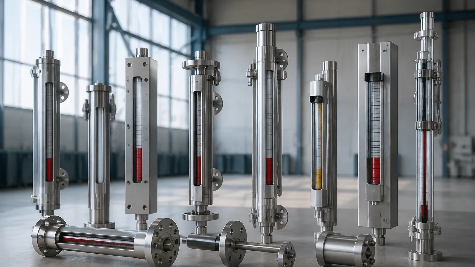
The float contains a high-intensity internal magnet assembly, typically arranged in a 360-degree ring to ensure consistent field strength regardless of float rotation. Mounted to the exterior of the chamber is an indicator rail. This rail contains a series of bi-color magnetic flaps or rollers (usually red and white or yellow and black).
As the float moves past these flaps, the magnetic field causes the flaps to rotate 180 degrees. This change in color creates a clear, high-contrast visual representation of the liquid level. Because the indicator is completely isolated from the process fluid, there is no risk of leaks, clouding, or glass breakage, which are common failure points in older sight glass designs.
Technical Specifications and Selection of X Gauges
Selecting the correct configuration for x gauges requires a detailed understanding of the process environment. Because these instruments are mechanical, their performance is directly tied to the physical properties of the fluid and the vessel's operating conditions.
Material Compatibility
The chamber material must be resistant to the corrosive nature of the process fluid. Common materials include:
* Stainless Steel (304/316L): The standard for water treatment and general industrial use.
* PTFE/PFA Lining: Essential for highly aggressive acids or ultrapure chemicals where metallic contamination must be avoided.
* Special Alloys: Materials like Hastelloy or Titanium are utilized in high-temperature or high-salinity environments.
Float Engineering
The float is the most critical component. It must be weighted precisely to match the specific gravity (SG) of the liquid. If the SG is too low (e.g., liquefied gases), the float must be larger or made of lighter materials like titanium to maintain buoyancy. Conversely, high-pressure applications require thicker-walled floats that can resist crushing, which in turn necessitates stronger magnets to overcome the increased distance between the float and the indicator.
Selection Table for Local Level Gauges
| Feature | Standard Magnetic Gauge | High-Pressure Variant | Cryogenic/Low Temp | Chemical Resistant (Lined) |
| :— | :— | :— | :— | :— |
| Pressure Range | Up to 40 bar | Up to 200+ bar | Up to 25 bar | Up to 16 bar |
| Temperature Range | -20°C to 200°C | -50°C to 450°C | Down to -196°C | -20°C to 120°C |
| Specific Gravity | > 0.60 | > 0.45 | > 0.40 | > 0.80 |
| Max Height | 6 meters (single section) | 4 meters | 6 meters | 4 meters |
| Indicator Type | Bi-color Flaps | Bi-color Flaps | Frost-protected Scale | Bi-color Flaps |
Installation Best Practices for Local Level Indicators
To ensure the accuracy and longevity of x gauges, precise installation is required. Improper mounting can lead to float sticking or inaccurate readings.
Alignment and Support
The bypass chamber must be installed perfectly vertical. Even a slight tilt can cause the float to rub against the chamber walls, leading to mechanical wear or "stiction" (static friction), where the float fails to move smoothly with level changes. For gauges exceeding 3 meters in length, intermediate support brackets are mandatory to prevent vibration and structural stress on the process nozzles.
Venting and Draining
Every magnetic level gauge should be equipped with a vent valve at the top and a drain valve at the bottom. These allow for:
1. Commissioning: Removing air pockets during initial fill.
2. Maintenance: Safely draining the chamber for cleaning or float inspection without depressurizing the main vessel.
3. Flushing: Clearing out accumulated sediment or scale that might interfere with float movement.
Insulation and Heat Tracing
In applications involving high-viscosity fluids (like heavy oils) or fluids that may crystallize at ambient temperatures, insulation jackets or steam/electric heat tracing should be applied to the chamber. This ensures the fluid remains at a consistent temperature, maintaining the correct specific gravity and viscosity for the float to operate.
Operational Limitations and Maintenance Requirements
While x gauges are highly durable, they are not universal solutions for every application. Understanding their limitations is key to process safety.
Magnetic Interference
Because the system relies on magnetic coupling, the presence of external magnetic fields or large amounts of ferrous particulate (iron filings, rust) in the fluid can interfere with the float. Ferrous debris can accumulate on the float's magnet, increasing its weight and eventually causing it to sink or jam. In such cases, a magnetic trap should be installed upstream of the gauge.
Viscosity and Solids
High-viscosity liquids (typically above 500 cP) can slow the response time of the float or cause it to stick. Similarly, fluids with a high solids content or those prone to heavy scaling can coat the float and chamber walls, necessitating frequent cleaning. For these applications, ultrasonic or radar level sensors may be more appropriate, though they lack the purely mechanical visual backup of a magnetic gauge.
Maintenance Checklist
* Monthly: Visually inspect the indicator rail for damaged flaps or moisture ingress behind the glass cover.
* Quarterly: Operate the drain valve briefly to flush out any sediment.
* Annually: If the process allows, remove the float to inspect for signs of corrosion, pitting, or mechanical wear. Verify that the float still moves freely within the chamber.
Frequently Asked Questions
Can magnetic level gauges be used for interface measurement?
Yes. By engineering a float with a density that falls between the specific gravities of two immiscible liquids (e.g., oil and water), the gauge can accurately track the interface level. The float will sink through the upper, lighter liquid and float on the lower, heavier liquid.
What happens if the float is installed upside down?
If the float is inverted, the internal magnet assembly will not align correctly with the indicator flaps. This usually results in the indicator showing a full or empty state regardless of the actual level, or the flaps may fail to flip entirely. Most floats are clearly marked with "TOP" to prevent this error.
Are these gauges suitable for high-vibration environments?
Standard magnetic gauges can be sensitive to extreme vibration, which may cause the flaps to rattle or flip falsely. For these environments, manufacturers offer "vibration-dampened" indicators or weighted flags that require a stronger magnetic pull to rotate, ensuring the reading remains stable.
Can I add electronic output to a local gauge?
One of the primary advantages of x gauges is their modularity. You can easily strap a reed-chain transmitter or a magnetostrictive sensor to the outside of the chamber. This allows the instrument to provide both a local visual display and a 4-20mA or HART signal to the control room without additional vessel penetrations.
How do I choose between a glass sight gauge and a magnetic gauge?
Glass sight gauges are generally lower in initial cost but carry higher risks of breakage and leaks. Magnetic gauges are preferred for hazardous, high-pressure, or high-temperature fluids where operator safety and environmental containment are priorities. For modern industrial facilities, the magnetic gauge is the standard choice for local level indication.
By adhering to these engineering guidelines and understanding the specific requirements of the process media, engineers can implement local level measurement solutions that provide reliable, long-term service in even the most demanding industrial environments.