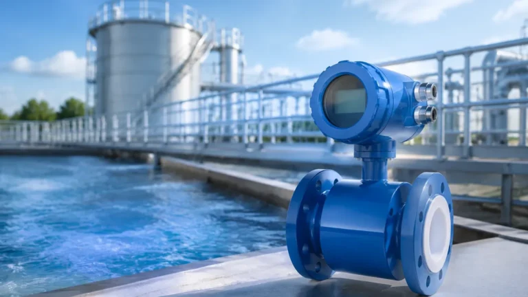
Hydrocarbon Processing Analysis Equipment
Hydrocarbon Processing Analysis Equipment
In the complex environment of oil refineries, petrochemical plants, and natural gas processing facilities, the accuracy of hydrocarbon processing analysis equipment is fundamental to operational safety and economic efficiency. Hydrocarbons present unique challenges for level measurement due to their varying dielectric constants, high volatility, and the extreme temperatures and pressures often found in process vessels. Selecting the correct instrumentation requires a deep understanding of the physical properties of the media and the mechanical constraints of the application.
This guide examines the primary technologies used for level measurement in hydrocarbon processing, providing engineering insights into their principles, selection criteria, and installation requirements.
Core Measurement Principles for Hydrocarbon Level Detection
Before selecting specific hydrocarbon processing analysis equipment, it is essential to understand the physics behind the most common measurement technologies. Each principle interacts differently with the physical properties of hydrocarbons, such as density and dielectric constant (εr).
Radar Level Measurement (Non-Contact and Guided)
Radar technology is the most prevalent solution in modern hydrocarbon processing. It operates on the Time of Flight (ToF) principle, where electromagnetic pulses are emitted, reflected off the liquid surface, and received by the sensor.
* Non-Contact Radar (FMCW): Frequency Modulated Continuous Wave (FMCW) radar, particularly at high frequencies like 80 GHz, provides a narrow beam angle. This is critical in hydrocarbon tanks where internal obstructions (heating coils, agitators) are common. Because radar waves are electromagnetic, they are unaffected by vacuum, pressure, or temperature changes in the vapor space.
* Guided Wave Radar (GWR): GWR uses a physical probe (rod or cable) to guide the radar pulse to the surface. This is highly effective for hydrocarbons with low dielectric constants (εr < 2.0), as the probe concentrates the energy, ensuring a detectable return signal even from poorly reflective surfaces.
Ultrasonic Level Measurement
Ultrasonic sensors emit high-frequency sound waves. The time taken for the echo to return is proportional to the distance. While cost-effective, ultrasonic technology is often limited in hydrocarbon processing because sound speed is affected by the composition and temperature of the vapor space (e.g., heavy hydrocarbon vapors), which can lead to significant measurement errors.
Hydrostatic Pressure Measurement
This method measures the pressure exerted by the liquid column. The level is calculated using the formula: *Level = Pressure / (Density × Gravity)*. In hydrocarbon processing, density often fluctuates with temperature. Therefore, hydrostatic systems must be paired with temperature compensation or used in applications where density remains constant to maintain accuracy.
Magnetic Level Gauges (MLG)
MLGs utilize a float containing a magnet assembly that moves with the liquid level inside a bypass chamber. As the float moves, it flips magnetic flags or interacts with a magnetostrictive transmitter. This provides both a visual indication and an electronic signal, making it a robust choice for high-pressure separators and storage tanks.
Selection Criteria for Hydrocarbon Applications
Choosing the right hydrocarbon processing analysis equipment depends on several process variables. Hydrocarbons are typically non-conductive and often have low dielectric constants, which influences the signal strength for radar-based instruments.
1. Dielectric Constant (εr): Most hydrocarbons have a dielectric constant between 1.4 and 2.5. Standard non-contact radar may struggle with εr < 1.9 unless high-sensitivity electronics or GWR are used.
2. Process Pressure and Temperature: Refineries often operate at pressures exceeding 100 bar (1450 psi) and temperatures above 400°C (752°F). Instruments must be rated for these extremes, often requiring specialized seals (e.g., Kalrez or ceramic) and cooling fins for electronics.
3. Vapor Space Composition: The presence of steam, heavy vapors, or gas blankets (like Nitrogen) can attenuate signals. High-frequency radar is generally the most resistant to these factors.
4. Interface Measurement: In many hydrocarbon processes, measuring the interface between oil and water is required. GWR is the industry standard for this, as the radar pulse partially reflects off the upper hydrocarbon layer and fully reflects off the lower aqueous layer.
Technical Selection Table
The following table provides a comparison of common technologies used in hydrocarbon processing analysis equipment.
| Technology | Accuracy | Dielectric Range (εr) | Max Temperature (Typical) | Max Pressure (Typical) | Best Use Case |
| :— | :— | :— | :— | :— | :— |
| 80 GHz Radar | ±1 mm | > 1.4 | -40 to +450°C | Up to 160 bar | Bulk storage, volatile liquids |
| Guided Wave Radar | ±2 mm | > 1.2 | -196 to +450°C | Up to 400 bar | Interface, low εr fluids, bypass pipes |
| Magnetic Gauge | ±5 mm | N/A | -196 to +400°C | Up to 320 bar | High-pressure boilers, separators |
| Hydrostatic | ±0.1% FS | N/A | -40 to +120°C | Dependent on sensor | Constant density tanks, open sumps |
| Ultrasonic | ±0.25% FS | N/A | -40 to +80°C | Up to 3 bar | Water treatment, non-volatile sumps |
Installation and Engineering Best Practices
Even the most advanced hydrocarbon processing analysis equipment will fail if installed incorrectly. Engineers should adhere to the following guidelines:
* Nozzle Geometry: For non-contact radar, the nozzle height should be minimized to prevent signal interference. The diameter of the nozzle should be sufficient to accommodate the beam angle of the radar. For 80 GHz radar, smaller nozzles are often acceptable due to the narrow beam.
* Bypass Chambers and Stilling Wells: In tanks with heavy turbulence or foam, installing the level sensor inside a stilling well or a side-mounted bypass chamber is recommended. This provides a calm surface for measurement and protects the instrument from mechanical stress.
* Grounding and Lightning Protection: Since many hydrocarbon facilities are located in open areas, instruments should be properly grounded and equipped with surge protection to prevent damage from atmospheric discharges.
* Seal Selection: Hydrocarbons are often aggressive solvents. Ensure that O-rings and gaskets are chemically compatible. For example, Viton is common, but extreme temperature applications may require graphite or metal-to-metal seals.
For a comprehensive review of instrument specifications and technical support for these applications, users should consult the Main Page of the manufacturer’s technical resource.
Limitations and Operational Risks
While modern instrumentation is highly reliable, certain conditions can compromise the performance of hydrocarbon processing analysis equipment:
* Heavy Coating and Buildup: In crude oil or bitumen applications, paraffin or wax buildup on probes (in GWR) or lenses (in non-contact radar) can attenuate the signal. High-frequency radar with a flush-mounted antenna is less susceptible to this issue.
* Boiling and Turbulence: Rapid boiling or heavy agitation creates a non-reflective surface for radar and can cause erratic readings in ultrasonic sensors. Using a stilling well is the primary mitigation strategy.
* Density Fluctuations: As noted, hydrostatic sensors rely on constant density. If the hydrocarbon composition changes (e.g., switching from light to heavy crude), the level reading will drift unless the system is recalibrated or compensated.
* Minimum Dielectric Requirements: If the dielectric constant of the fluid drops below the instrument's minimum threshold, the signal will be lost. In these cases, a coaxial probe GWR or a magnetic level gauge is the only viable solution.
Frequently Asked Questions (FAQ)
Q: Can radar be used to measure the level of Liquefied Natural Gas (LNG)?
A: Yes, but it requires specialized equipment. LNG has a very low dielectric constant (approx. 1.7) and is stored at cryogenic temperatures (-162°C). High-sensitivity GWR or non-contact radar with cryogenic seals are the standard choices.
Q: Why is 80 GHz radar preferred over 26 GHz for hydrocarbon tanks?
A: 80 GHz radar has a much narrower beam (approx. 3° to 4° compared to 10°+ for 26 GHz). This allows it to avoid internal tank structures like ladders and pipes, and it handles low dielectric fluids more effectively by concentrating the signal energy.
Q: How do I measure the interface between oil and water in a separator?
A: Guided Wave Radar (GWR) is the most effective tool. The radar pulse passes through the upper hydrocarbon layer (low εr) and reflects off the water layer (high εr). The instrument calculates both the total level and the interface level simultaneously.
Q: Is ultrasonic equipment suitable for gasoline storage?
A: Generally, no. Gasoline is highly volatile, and the resulting vapor changes the speed of sound in the tank's headspace, leading to inaccurate readings. Non-contact radar is the preferred alternative for volatile hydrocarbons.
Conclusion
Effective management of hydrocarbon facilities relies on the precise integration of hydrocarbon processing analysis equipment. By understanding the relationship between the physical properties of the media—such as dielectric constant and density—and the measurement principle of the instrument, engineers can ensure long-term reliability and safety. Whether utilizing the precision of 80 GHz radar or the robustness of magnetic level gauges, proper selection and installation are the cornerstones of process optimization in the oil and gas industry.