Hopper Level Sensor
Hopper Level Sensor
In industrial bulk solids handling, the hopper serves as a critical buffer and distribution point for materials ranging from fine powders to heavy aggregates. Monitoring the contents of these vessels is essential for preventing overfills, ensuring a continuous supply to downstream processes, and optimizing inventory management. A hopper level sensor must contend with unique challenges not typically found in liquid storage, including high dust concentrations, uneven material surfaces (cones), and varying bulk densities.
Selecting the appropriate instrumentation requires a deep understanding of measurement principles and the physical characteristics of the stored media. This guide examines the primary technologies used for hopper level measurement, their operational mechanics, and the engineering considerations necessary for a successful installation.
Measurement Principles for Hopper Level Sensing
Level measurement in hoppers is generally categorized into two types: point level detection and continuous level measurement. Point level sensors indicate whether a material has reached a specific height, while continuous sensors provide a real-time tracking of the material level throughout the entire height of the vessel.
Point Level Detection (Switches)
Point level sensors are frequently used as high-level alarms to prevent overfilling or low-level alarms to protect feeders and conveyors from running empty.
1. Rotary Paddle Switches: These sensors utilize a low-speed electric motor that rotates a paddle. When the material reaches the paddle, it creates mechanical resistance, stalling the motor and triggering a microswitch. They are robust and unaffected by the dielectric properties of the material, making them ideal for heavy grains, sand, and plastic pellets.
2. Vibrating Probe/Tuning Fork: These sensors employ a rod or a fork-shaped element that vibrates at its natural frequency. When covered by bulk solids, the vibration is damped. The electronics detect this change in frequency or amplitude and toggle an output. These are highly sensitive and suitable for very light powders with low bulk densities.
3. RF Admittance/Capacitance: These sensors measure the electrical impedance between the sensor probe and the vessel wall. As material replaces air, the capacitance changes. Modern RF admittance sensors use a "guard" circuit to ignore material buildup on the probe, which is a common issue in dusty or sticky applications.
Continuous Level Measurement (Transmitters)
Continuous measurement allows operators to monitor the exact volume of material in the hopper at any given time.
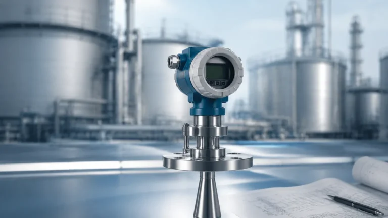
1. Non-Contact Radar (FMCW): Frequency Modulated Continuous Wave (FMCW) radar, particularly those operating at 80 GHz, is the gold standard for hopper level sensing. The sensor emits a high-frequency signal that reflects off the material surface. By measuring the frequency shift of the returned signal, the distance is calculated with high precision. The narrow beam angle of 80 GHz radar allows it to avoid internal obstructions like ladders or reinforcements.
2. Ultrasonic Sensors: These devices emit a sound pulse that reflects off the material. The time-of-flight is used to determine the distance. While cost-effective, ultrasonic sensors can struggle in hoppers with high dust levels, as the dust particles can absorb or scatter the sound waves. They are also sensitive to air temperature fluctuations.
3. Guided Wave Radar (GWR): GWR uses a cable or rod probe to guide a microwave pulse to the material surface. It is highly accurate and unaffected by dust or vapor. However, in hoppers, the mechanical pull-down forces (tensile load) exerted by moving solids on the cable must be carefully calculated to prevent structural failure of the sensor or the hopper roof.
Key Evaluation Criteria for Sensor Selection
When choosing a hopper level sensor, engineers must evaluate several variables to ensure long-term reliability. For a comprehensive overview of available technologies and technical specifications, you may Review product options and application support at the Welk Main Page.
Material Characteristics
* Bulk Density: Light materials (like fumed silica) may not provide enough resistance for a rotary paddle or enough reflection for an ultrasonic sensor.
* Dielectric Constant (εr): For radar and RF sensors, the dielectric constant of the material determines the strength of the reflected signal. Materials with low εr, such as plastic pellets, require high-sensitivity radar electronics.
* Moisture Content: Changes in moisture can cause material to stick to the hopper walls or the sensor probe, leading to false readings in capacitance-based systems.
* Particle Size and Abrasiveness: Large, abrasive rocks can damage contact-based probes or paddles.
Hopper Geometry and Environment
* Angle of Repose: Bulk solids do not sit flat; they form a cone (filling) or a crater (emptying). The sensor must be positioned to account for this profile to provide an accurate average level.
* Internal Obstructions: Cross-braces, agitators, and ladders can create false echoes. Sensors with narrow beam angles or advanced "false echo suppression" software are required.
* Dust and Turbulence: Filling processes often create significant dust. Radar is generally immune to dust, whereas ultrasonic sensors may fail if the signal is attenuated by the airborne particles.
Practical Selection Table
| Technology | Best Suited For | Key Advantage | Limitation |
| :— | :— | :— | :— |
| 80 GHz Radar | Fine powders, grains, varying solids | High accuracy, penetrates dust, narrow beam | Higher initial cost |
| Ultrasonic | Large pellets, low-dust environments | Cost-effective, non-contact | Affected by dust and temperature |
| Rotary Paddle | Heavy solids, sand, gravel | Simple, robust, unaffected by εr | Mechanical wear, point level only |
| Vibrating Probe | Light powders, flour, fly ash | No moving parts, high sensitivity | Can be damaged by heavy/falling material |
| RF Admittance | Sticky materials, liquids/solids interface | Ignores material buildup | Requires calibration for different materials |
Installation Considerations and Best Practices
Proper installation is as critical as sensor selection. Even the most advanced sensor will provide poor data if mounted incorrectly.
1. Nozzle Height and Diameter: For non-contact radar and ultrasonic sensors, the mounting nozzle should be as short as possible. If the nozzle is too long or narrow, the signal may reflect off the nozzle walls before reaching the material, creating a "near-zone" interference.
2. Positioning Relative to the Fill Stream: Never mount a sensor directly in the path of the incoming material. This will not only cause erratic readings but can also physically damage the instrument.
3. Aiming for the Cone: Because solids form a cone, mounting the sensor at 1/6th to 1/3rd of the diameter from the side wall usually provides the most representative measurement of the average volume. Some radar sensors include swiveling flanges to aim the beam at the discharge outlet for better tracking during emptying.
4. Structural Integrity: For Guided Wave Radar, the tensile load on the probe can reach several thousand kilograms in tall hoppers. Ensure the mounting point is reinforced and that the probe is rated for the expected pull-down forces.

Common Risks and Limitations
* Signal Loss in Low Dielectrics: If the material has a very low dielectric constant (εr < 1.5), the radar signal may pass through the material and reflect off the bottom of the hopper instead. In these cases, specialized high-sensitivity antennas or GWR are necessary.
* Acoustic Noise: In heavy industrial environments, mechanical noise from crushers or vibrators can interfere with the operating frequency of ultrasonic sensors.
* Condensation: In outdoor hoppers, temperature shifts can cause condensation on the sensor face. While radar can typically see through thin films of moisture, heavy droplets can cause signal scattering. Sensors with PTFE-faced antennas are often used to encourage moisture shedding.
Frequently Asked Questions (FAQs)
Q: Can a radar sensor measure the level of plastic pellets accurately?
A: Yes, but since plastic has a low dielectric constant, an 80 GHz radar with high dynamic range is recommended to ensure a strong enough reflection from the surface.
Q: How do I handle dust buildup on the sensor face?
A: Many radar sensors feature a flat-face design that minimizes the area where dust can collect. For extreme cases, air purge connections can be used to blow a continuous stream of clean air across the sensor face to keep it clear.
Q: Is it better to use a single continuous sensor or multiple point level switches?
A: For process control and inventory, continuous measurement is superior. However, for safety-critical overfill prevention, many regulations require an independent point level switch (like a rotary paddle) to act as a redundant backup to the continuous transmitter.
Q: What is the maximum range for a hopper level sensor?
A: Modern radar transmitters can measure distances up to 30 meters (approx. 100 feet) or more, which covers the vast majority of industrial hopper and silo applications.
Conclusion
Effective hopper level management is a balance of selecting the right physics for the material and ensuring the installation accounts for the mechanical realities of bulk solids handling. While point level switches offer a simple and robust solution for basic alarms, the transition toward 80 GHz radar technology has provided industries with unprecedented accuracy and reliability in continuous monitoring, even in the most challenging dust-filled environments.
Before finalizing a specification, engineers should confirm the material's bulk density, dielectric properties, and the hopper's internal structural layout. For technical assistance and to explore a full range of industrial measurement solutions, visit the Welk Main Page for detailed product data and application engineering support.