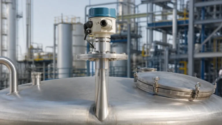
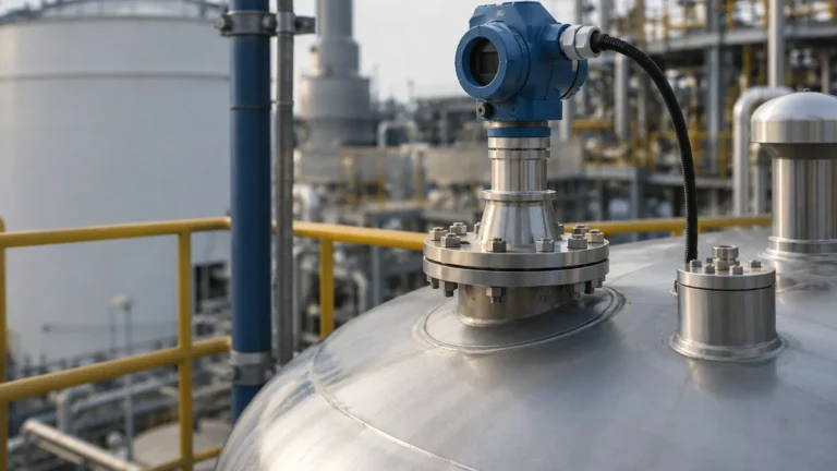
Radar Level Transmitter Abb
Radar Level Transmitter ABB: An Engineering Guide to Selection and Application
In the landscape of industrial automation, the demand for precise, non-contact level measurement has led to the widespread adoption of radar technology. Whether evaluating a radar level transmitter ABB series or alternative high-performance Radar Level Meters, engineers must navigate complex variables including frequency, antenna design, and process conditions. This guide provides a technical overview of radar level measurement principles, selection criteria, and installation best practices for B2B industrial applications.
1. Understanding Radar Measurement Principles
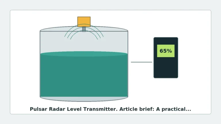
Radar level measurement is based on the Time-of-Flight (ToF) principle. The instrument emits electromagnetic waves (microwaves) toward the surface of the medium. These waves are reflected back to the sensor, and the distance is calculated based on the time elapsed between emission and reception. In industrial settings, two primary methods are utilized: Pulse Radar and Frequency Modulated Continuous Wave (FMCW).
Pulse Radar (Time-of-Flight)
Pulse radar transmitters emit short microwave pulses at a fixed frequency. The device measures the time it takes for a single pulse to travel to the surface and return. While effective for many standard applications, pulse radar can sometimes struggle with low-dielectric materials or turbulent surfaces where the return signal is weak.
FMCW (Frequency Modulated Continuous Wave)
FMCW technology is generally considered superior for high-precision requirements. Instead of pulses, the transmitter emits a continuous signal with a constantly changing frequency (a linear sweep). The reflected signal is compared to the emitted signal at that moment. The difference in frequency ($Δf$) is directly proportional to the distance. FMCW offers a higher signal-to-noise ratio, making it the preferred choice for complex environments such as those involving narrow nozzles or internal tank obstructions.
2. Guided Wave Radar vs. Non-Contact Radar
When selecting a radar level transmitter ABB or similar industrial grade instrument, the first architectural decision is between guided wave and non-contact designs.
| Feature | Non-Contact Radar | Guided Wave Radar (GWR) |
| :— | :— | :— |
| Measurement Path | Through air/vapor space | Along a physical probe (rod/cable) |
| Surface Sensitivity | Sensitive to foam and turbulence | Less sensitive to surface conditions |
| Maintenance | Extremely low (no moving/wetted parts) | Low (requires probe cleaning if sticky) |
| Installation | Top-down, clear path required | Requires probe length to match tank height |
| Dielectric Constant | Requires εr > 1.4 typically | Can measure εr as low as 1.2 |
Non-contact Radar Level Meters are ideal for corrosive or hygienic applications where the sensor must not touch the medium. Guided Wave Radar is often preferred for interface measurement (e.g., oil over water) or in tanks with heavy steam and dust.
3. Key Selection Criteria for Industrial Radar
To ensure the reliability of a radar level transmitter ABB system or equivalent, procurement and engineering teams must confirm several technical parameters.
Frequency Bands
Frequency determines the beam angle and the ability of the radar to penetrate dust or vapor.
- 6 GHz (C-Band): Best for heavy foam or turbulent surfaces, but requires large antennas to maintain a narrow beam.
- 26 GHz (K-Band): The industrial standard. It offers a balance between small antenna size and good signal focusing.
- 80 GHz (W-Band): Provides the narrowest beam angle (down to 3°). This is excellent for tall, narrow silos or tanks with many internal obstructions like agitators and heating coils.
Dielectric Constant (εr)
The dielectric constant of the medium is the most critical factor in signal reflection. Materials with high εr (e.g., water, εr ≈ 80) reflect signals strongly. Hydrocarbons like oil or diesel (εr ≈ 2.0) reflect much less energy. If the εr is below 1.5, specialized high-sensitivity radar or guided wave technology is mandatory.
Process Temperature and Pressure
Industrial radar transmitters must withstand the vessel's environment. Standard units often handle up to 150°C and 40 bar (4.0 MPa). For high-pressure boilers or chemical reactors, specialized ceramic seals and cooling fins are required to protect the electronics from temperatures exceeding 400°C.
4. Installation Considerations and Constraints
Even the most advanced radar level transmitter ABB provides will fail if installed incorrectly. Engineers should adhere to the following checklists during the design phase.
The Beam Angle and Obstructions
The radar signal spreads in a cone shape. Any metal object within this cone (ladders, pipes, agitator blades) will create a "false echo."
- Calculation: The diameter of the footprint can be calculated as $D = 2 · L · tan(α/2)$, where $L$ is the distance and $α$ is the beam angle.
- Solution: Use "False Echo Mapping" software features to tell the transmitter to ignore these static reflections.
Nozzle Geometry
The nozzle (the pipe section where the radar is mounted) should be as short and wide as possible. If the nozzle is too long, the radar signal may reflect off the internal weld seams of the pipe before it even enters the tank, creating a "dead zone" at the top of the measurement range.
Minimum Distance (Blocking Distance)
Every radar sensor has a minimum measurable distance, usually 50mm to 200mm from the antenna tip. If the liquid level rises into this zone, the measurement will become erratic or lock at the maximum value.
5. Technical Specification Table
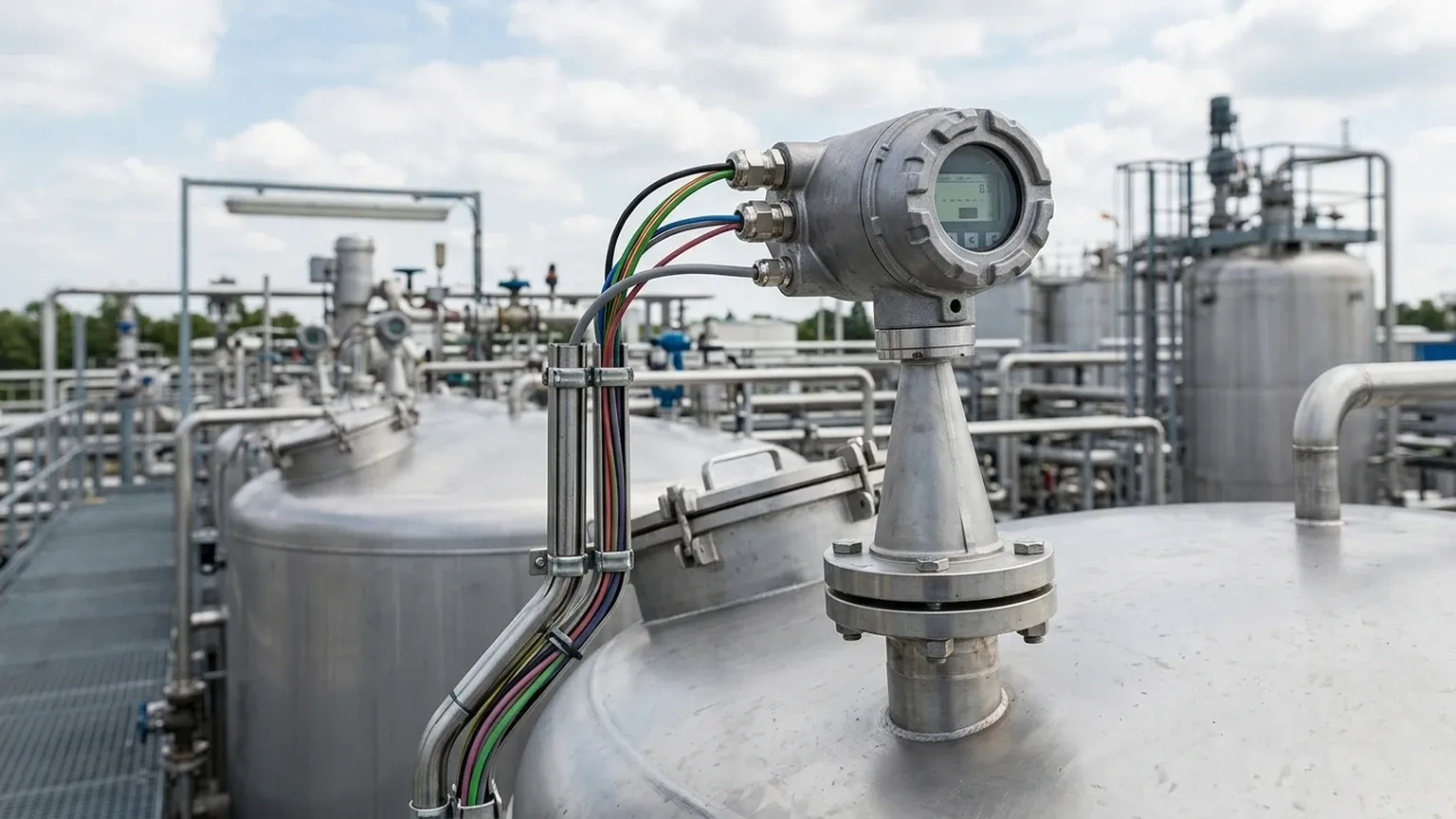
| Parameter | Standard Industrial Radar | High-Precision Radar |
| :— | :— | :— |
| Accuracy | ±3 mm to ±5 mm | ±0.5 mm to ±1 mm |
| Measuring Range | Up to 30 meters | Up to 120 meters |
| Output Signal | 4-20mA HART, Modbus | 4-20mA HART, Profibus, Foundation Fieldbus |
| Housing Material | Aluminum or Plastic | 316L Stainless Steel |
| Antenna Type | Horn, Rod, or Lens | Parabolic or Flange-flush Lens |
6. Limitations and Application Risks
While radar is highly versatile, it is not a universal solution. Engineers must be aware of specific limitations:
1. Heavy Foam: Dense, thick foam (like shaving cream) can absorb the radar signal entirely, resulting in a "Loss of Echo" (LOE) error. In these cases, ultrasonic or hydrostatic sensors may be more reliable.
2. Vacuum Conditions: While radar works in a vacuum (unlike ultrasonic sensors), the mechanical seals of the transmitter must be rated for vacuum to prevent air ingress or sensor damage.
3. Multiple Reflections: In small, spherical tanks, the radar signal can bounce off the curved walls multiple times, creating ghost signals. High-frequency 80 GHz radar is typically used to mitigate this through a narrower focus.
7. Maintenance and Calibration
Modern radar level transmitters are designed for "fit and forget" operation. However, annual verification is recommended for regulated industries (e.g., oil and gas custody transfer or chemical safety).
- Verification: Compare the radar reading against a manual dip tape measurement.
- Cleaning: If the medium is prone to crystallization or condensation, the antenna may require periodic cleaning. Some high-end models include a compressed air purging connection to clean the antenna automatically.
8. Frequently Asked Questions (FAQ)
Q: Can a radar level transmitter measure through a plastic tank roof?
A: Yes. Because plastic is non-conductive and has a low dielectric constant, radar signals can penetrate the roof of a plastic (HDPE or PP) tank, allowing for measurement without cutting a hole in the vessel. This is common in chemical IBC monitoring.
Q: How does the radar level transmitter ABB handle agitators?
A: Most industrial radars use an algorithm called "Agitator Mapping." The transmitter learns the position of the blades as they rotate and filters out those specific intermittent reflections from the final level calculation.
Q: Is 80 GHz always better than 26 GHz?
A: Not necessarily. While 80 GHz offers better focus, 26 GHz is often more robust in applications with heavy condensation or steam, as the longer wavelength is less affected by water droplets on the antenna lens.
Q: What information is needed for a quote?
A: To specify a radar unit, you must provide the medium name, dielectric constant, tank height, process temperature, process pressure, and the size/type of the mounting connection (flange or thread).
For professional assistance in selecting the correct instrumentation for your facility, explore the technical specifications of various Radar Level Meters to match your specific process requirements.