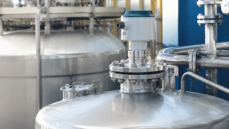
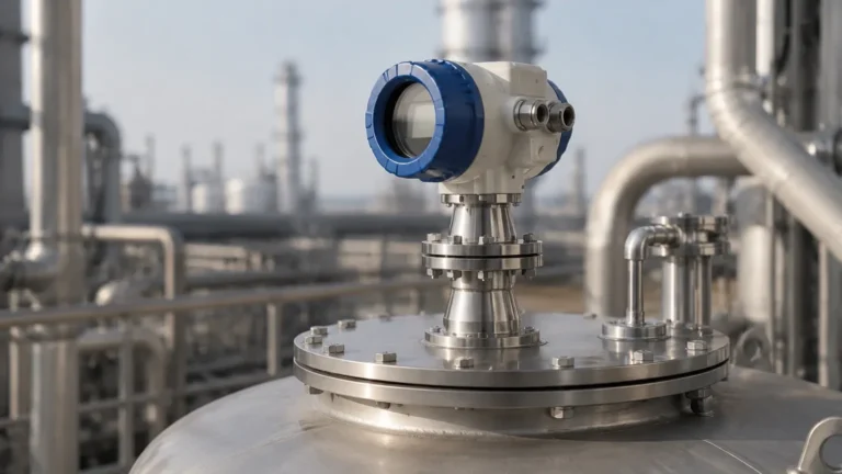
Radar Level Transmitter Antenna
Radar Level Transmitter Antenna: A Technical Engineering Guide to Selection and Application
In industrial process automation, the accuracy of a level measurement system is fundamentally dependent on the interface between the instrument and the process environment. For non-contacting radar systems, this interface is the radar level transmitter antenna. The antenna is responsible for focusing electromagnetic energy into a beam, transmitting it toward the material surface, and capturing the reflected return signal. Choosing the correct antenna geometry and material is critical for ensuring signal integrity, especially in challenging environments characterized by turbulence, foam, or internal tank obstructions.
As a professional manufacturer, Welk provides a range of Radar Level Meters designed to meet diverse industrial requirements. This guide explores the engineering principles of radar antennas, selection criteria for various process conditions, and best practices for installation.
1. Measurement Principles and the Role of the Antenna
Radar level measurement operates on the principle of Time Domain Reflectometry (TDR) or Frequency Modulated Continuous Wave (FMCW). In both methods, the antenna serves as the transducer that converts electrical high-frequency signals into electromagnetic waves.
1.1 Signal Propagation and Beamwidth
The antenna determines the "beam angle" of the radar signal. A narrower beam angle concentrates more energy on the target surface and reduces the likelihood of interference from tank walls, agitators, or ladders. The beam angle is a function of both the antenna's physical diameter and the operating frequency (typically 6 GHz, 26 GHz, or 80 GHz). Higher frequencies allow for smaller antenna sizes while maintaining a narrow beam.
1.2 Dielectric Constant ($ε_r$)
The strength of the reflected signal is directly proportional to the dielectric constant of the medium. Materials with low $ε_r$ (such as hydrocarbons or solids) reflect less energy. In these applications, the radar level transmitter antenna must be highly efficient, often requiring larger horn diameters or parabolic shapes to maximize signal recovery.
2. Types of Radar Level Transmitter Antennas
Antenna design is categorized based on the physical shape and the method used to focus the microwave energy. Each type has specific advantages depending on the medium and vessel geometry.
2.1 Horn (Conical) Antennas
The horn antenna is the most versatile and widely used design in the industry. It consists of a flared metal cone that transitions the microwave signal from the waveguide to free space.
- Applications: Best suited for liquid level measurement in large tanks.
- Advantages: Robust, capable of handling high temperatures (up to 400°C) and pressures (up to 160 bar), and relatively easy to clean.
- Limitations: Requires a nozzle diameter large enough to accommodate the horn flare.
2.2 Rod Antennas
Rod antennas are typically constructed from synthetic materials like PTFE (Polytetrafluoroethylene) or PFA. The signal travels along the length of the rod and is emitted from the tip.
- Applications: Ideal for corrosive liquids, acids, and small-diameter nozzles (typically DN50 or smaller).
- Advantages: Excellent chemical resistance and a slim profile.
- Limitations: Generally limited to lower pressure and temperature ranges compared to stainless steel horn antennas. They are also more susceptible to heavy condensation or buildup.
2.3 Parabolic Antennas
Parabolic antennas use a large dish-shaped reflector to focus the radar signal into a very narrow beam, typically between 4° and 6°.
- Applications: Primarily used for solids, powders, and low-dielectric materials over long distances (up to 70 meters or more).
- Advantages: Maximum signal gain and minimal interference from internal tank structures.
- Limitations: Susceptible to dust accumulation on the reflector surface; often requires an integrated air-purge system.
2.4 Lens (Planar) Antennas
Modern 80 GHz radar systems often utilize lens antennas. These are flush-mounted designs where a polymer lens focuses the high-frequency signal.
- Applications: High-precision measurement, pharmaceutical applications, and vessels with narrow nozzles or heavy condensation.
- Advantages: The flush design prevents material buildup and allows for measurement through plastic tank lids. The narrow beam (down to 3°) avoids almost all internal obstructions.
3. Engineering Selection Criteria
Selecting the appropriate radar level transmitter antenna requires a detailed analysis of the process environment. The following table provides a comparison based on typical industrial parameters.
| Antenna Type | Frequency Range | Beam Angle (Approx.) | Temperature Range | Pressure Range | Best Use Case |
| :— | :— | :— | :— | :— | :— |
| Small Horn | 26 GHz | 15° – 20° | -40 to +250°C | Up to 40 bar | Standard liquid storage |
| Large Horn | 26 GHz | 8° – 12° | -40 to +400°C | Up to 160 bar | Deep tanks, low $ε_r$ liquids |
| PTFE Rod | 6 / 26 GHz | 20°+ | -40 to +150°C | Up to 16 bar | Acids, corrosive chemicals |
| Parabolic | 26 GHz | 4° – 6° | -40 to +200°C | Up to 3 bar | Solids, grains, long-range |
| Lens (Flush) | 80 GHz | 3° – 8° | -40 to +200°C | Up to 25 bar | High precision, narrow nozzles |
3.1 Material Compatibility
The wetted parts of the antenna must be compatible with the process medium. While 316L stainless steel is the standard, aggressive media may require Hastelloy C, Monel, or full PTFE cladding. Welk offers customized material options to ensure long-term durability in chemical processing environments.
3.2 Beam Angle and Obstructions
Engineers must calculate the "footprint" of the radar beam at the lowest point of the tank. If the beam hits a heating coil or an agitator blade, it will create a false echo. A narrower beam angle provided by a larger antenna or higher frequency (80 GHz) is the primary solution for avoiding these obstacles.
4. Installation Considerations and Constraints
Proper installation is as important as antenna selection. Even the most advanced radar level transmitter antenna will fail if positioned incorrectly.
4.1 Nozzle Geometry
The antenna should ideally extend beyond the mounting nozzle. If a horn antenna is retracted inside a long nozzle, the microwave signal will reflect off the nozzle walls, creating a "ringing" effect that masks the true level signal near the top of the tank. For long nozzles, an antenna extension or a flush-mounted lens antenna should be used.
4.2 Positioning
- Wall Distance: The antenna should be installed at a distance of approximately 1/6 of the tank diameter from the wall. Placing it too close to the wall causes interference, while placing it in the dead center can lead to multiple reflections in tanks with domed roofs.
- Inlet Avoidance: Never install the antenna directly over the product inlet, as the falling stream will cause erratic readings.
- Vortex Considerations: In tanks with agitators, the liquid surface may form a vortex. The antenna should be positioned to avoid the steepest part of the slope to ensure a perpendicular reflection.
4.3 Orientation
For horn antennas, the polarization of the signal can sometimes be adjusted by rotating the instrument housing. This can help minimize reflections from specific obstructions like support beams.

5. Limitations and Application Risks
While radar technology is highly reliable, certain conditions can degrade antenna performance:
1. Heavy Foam: Dense, thick foam can absorb the radar signal entirely. In such cases, a low-frequency (6 GHz) radar with a large horn antenna may perform better than high-frequency versions, though hydrostatic or magnetic level gauges might be required as alternatives.
2. Condensation and Buildup: Moisture or product buildup on the antenna surface can attenuate the signal. PTFE-coated antennas or those with integrated air purges are recommended for these scenarios.
3. Vacuum Conditions: While radar works in a vacuum, the sealing of the antenna (the process seal) must be rated for vacuum service to prevent damage to the internal electronics.
4. Extreme Turbulence: Rapidly moving surfaces scatter the radar signal. Software algorithms (False Echo Suppression) can mitigate this, but a larger antenna is often needed to capture the scattered reflections.
6. Frequently Asked Questions (FAQ)
Q: Can I use a radar level transmitter antenna for both liquids and solids?
A: While some antennas are versatile, solids usually require a parabolic or a specialized high-frequency lens antenna due to the uneven surface and lower reflectivity of the material. Liquids are generally better served by horn or rod antennas.
Q: What is the benefit of an 80 GHz radar antenna over a 26 GHz one?
A: The primary benefit is the much narrower beam angle (3° vs. 10°) and a smaller physical size. This allows the 80 GHz antenna to be mounted in smaller nozzles and avoid internal tank obstructions more effectively.
Q: How do I maintain the antenna?
A: Most radar antennas are maintenance-free. However, in applications with heavy crystallization or dust, periodic cleaning may be necessary. If the antenna has an air purge connection, ensure the compressed air supply is clean and dry.
Q: Does the antenna length matter?
A: Yes. The antenna (especially horn types) should ideally be longer than the mounting nozzle to ensure the signal is launched into the tank without interference from the nozzle's internal edges.
7. Conclusion
The radar level transmitter antenna is the critical link in a non-contact level measurement system. By understanding the relationship between frequency, beam angle, and the physical properties of the process medium, engineers can select a solution that provides reliable data even in the harshest industrial environments.
For technical support in selecting the right antenna configuration for your specific application, or to explore our full range of instrumentation, visit our Radar Level Meters product page. Welk provides comprehensive OEM/ODM services and technical guidance to ensure your level measurement projects are successful and cost-effective.