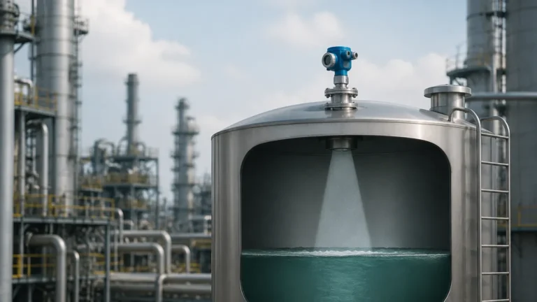
Radar Level Transmitter Calibration
Radar Level Transmitter Calibration: A Comprehensive Engineering Guide
In the landscape of industrial automation, precision is the cornerstone of safety and efficiency. Radar level measurement has emerged as a gold standard for non-contact level sensing in challenging environments, ranging from volatile chemical reactors to wastewater treatment facilities. However, the inherent accuracy of Radar Level Meters is only as reliable as the calibration and commissioning process.
This guide provides a technical deep dive into radar level transmitter calibration, exploring the physics of microwave measurement, the practical steps for field configuration, and the critical factors that international procurement officers and engineers must consider when selecting and maintaining these instruments.
Understanding Radar Measurement Principles
Before addressing calibration, it is essential to understand how radar instruments perceive distance. Radar level transmitters operate on the principle of microwave reflection. They emit high-frequency electromagnetic waves that travel through the vapor space, reflect off the surface of the medium, and return to the sensor.
Time of Flight (ToF) vs. FMCW
Most industrial radar transmitters utilize one of two primary technologies:
1. Pulse Radar (ToF): The device emits a short microwave pulse and measures the time it takes for the pulse to travel to the surface and back. Since the speed of light ($c$) is constant, the distance ($D$) is calculated as $D = (c \times t) / 2$, where $t$ is the transit time.
2. Frequency Modulated Continuous Wave (FMCW): The transmitter emits a continuous signal with a frequency that changes linearly over time (a frequency sweep). The reflected signal is compared to the signal being emitted at that moment. The difference in frequency (the "beat frequency") is directly proportional to the distance. FMCW is generally preferred for high-precision applications due to its superior signal-to-noise ratio.
The Role of the Dielectric Constant (εr)
The dielectric constant of the process material determines how much energy is reflected back to the sensor. Materials with high dielectric constants (e.g., water, $\epsilon_r \approx 80$) provide strong, clear reflections. Materials with low dielectric constants (e.g., hydrocarbons, $\epsilon_r < 2$) reflect very little energy, requiring more sensitive electronics and precise calibration to distinguish the surface echo from background noise.
The Calibration Process: Bench vs. Field
Calibration is the process of mapping the physical distance measured by the radar to a standardized output signal, typically 4-20 mA or a digital protocol like HART, Modbus, or PROFIBUS.
1. Factory and Bench Calibration
Before shipment, manufacturers perform a factory calibration to ensure the sensor's internal clock and electronics meet accuracy specifications. Bench calibration involves testing the unit in a controlled environment using a target at known distances. While this verifies the instrument is functional, it cannot account for the specific geometry and internal obstructions of the final installation site.
2. Field Commissioning and Configuration
True radar level transmitter calibration occurs during commissioning. This process involves setting the "Zero" and "Span" based on the actual tank dimensions.
* Lower Range Value (LRV / 4mA): This is usually the "Empty" point. It is the distance from the sensor's reference point (typically the flange face) to the bottom of the tank.
* Upper Range Value (URV / 20mA): This is the "Full" point. It is the distance from the reference point to the maximum desired liquid level. Note that this must account for the "Dead Zone" or "Blocking Distance"—the area immediately below the antenna where the device cannot measure.
Step-by-Step Radar Level Transmitter Calibration
To ensure an accurate and stable output, follow these technical steps during the configuration of a radar level transmitter:
Step 1: Establish the Reference Point
Identify the physical point on the transmitter from which all measurements are taken. For most flange-mounted radar meters, this is the bottom surface of the flange. For threaded units, it is often the base of the threads.
Step 2: Define Tank Geometry
Enter the total tank height into the transmitter's microprocessor. If the tank has a conical or dished bottom, the calibration must account for the volume-to-level non-linearity if the output is intended to represent volume rather than just height.
Step 3: Set the Range Limits
* Empty Calibration: Define the distance from the reference point to the 0% level. For example, in a 10-meter tank, if the sensor is mounted 0.5 meters above the maximum level, the empty distance might be 10.5 meters.
* Full Calibration: Define the distance to the 100% level. This should always be outside the device's blocking distance (typically 0.1m to 0.5m depending on the frequency and antenna type).
Step 4: False Echo Suppression (Mapping)
This is the most critical step in radar calibration. Every tank has internal obstructions such as ladders, agitators, or heating coils that create "parasitic reflections."
Modern radar software allows the user to perform an "Echo Curve" analysis. The transmitter records all reflections in an empty or partially empty tank and creates a "map" of these static interferences. The software then ignores any echoes that fall on this map, focusing only on the moving echo from the liquid surface.
Step 5: Adjusting for Dielectric and Turbulence
If the medium has a low dielectric constant or the surface is turbulent (due to an agitator), the sensitivity or "gain" of the transmitter may need adjustment. Increasing the damping value (e.g., to 10 or 30 seconds) can help smooth out the output signal in turbulent applications.
Selection Criteria for Radar Level Meters
Choosing the right hardware is a prerequisite for successful calibration. The following table outlines the primary considerations for different radar technologies.
| Feature | 6 GHz / 26 GHz Radar | 80 GHz Radar | Guided Wave Radar (GWR) |
| :— | :— | :— | :— |
| Best Use Case | Large tanks, heavy foam, or steam. | Narrow tanks, precision measurement, solids. | Small tanks, low dielectric liquids, interface measurement. |
| Beam Angle | Wide (approx. 10°–20°). | Narrow (approx. 3°–8°). | N/A (signal follows probe). |
| Installation | Requires clear path; sensitive to obstructions. | Easier to install in narrow nozzles or near walls. | Requires contact with the medium. |
| Accuracy | ±3 mm to ±10 mm. | ±1 mm to ±2 mm. | ±2 mm to ±5 mm. |
| Calibration Complexity | Moderate (Mapping is essential). | Low (Narrow beam avoids most noise). | High (Probe length and end-of-probe offsets). |
Installation Constraints and Best Practices
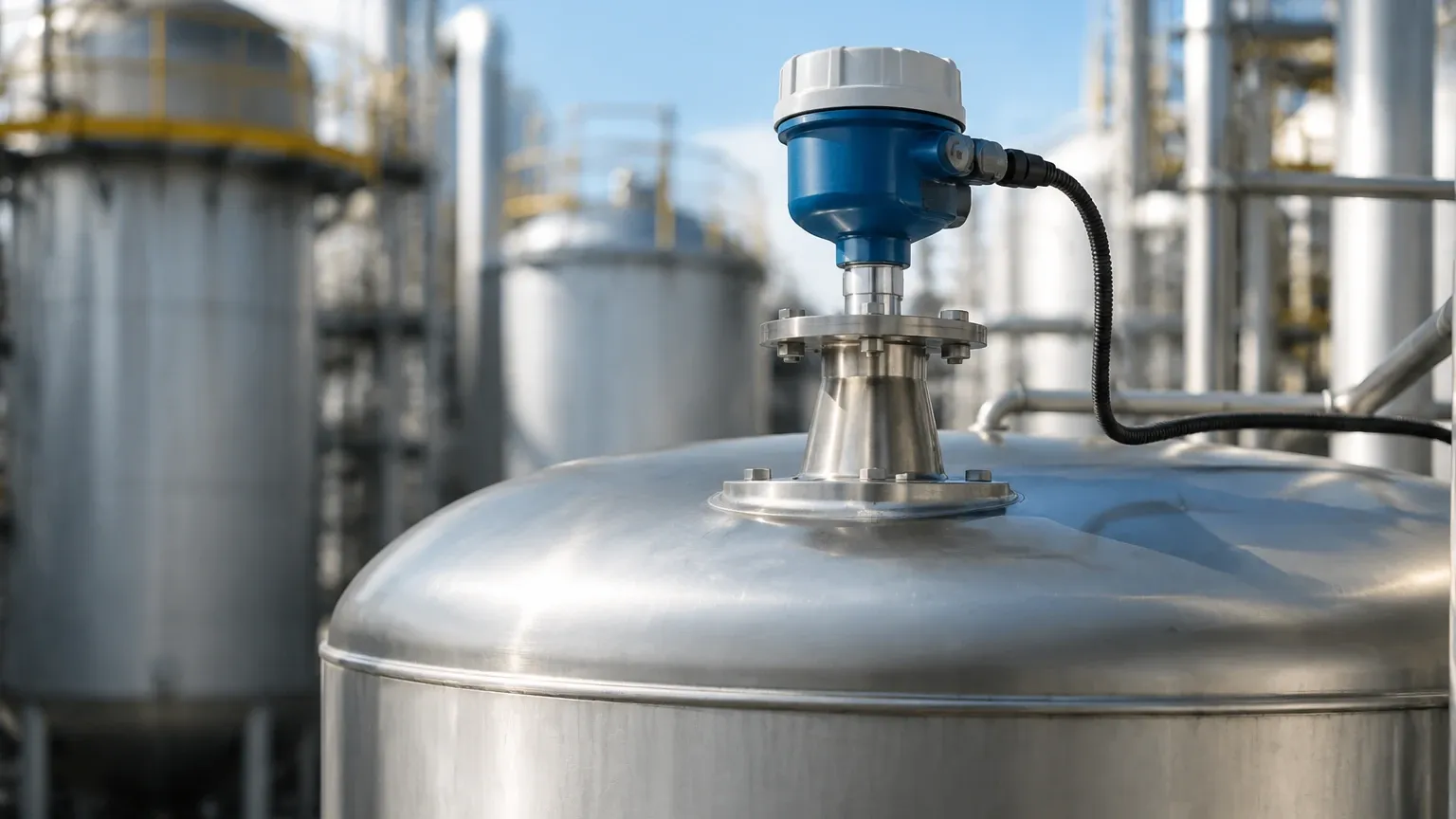
Even the most precise radar level transmitter calibration cannot compensate for poor installation. Engineers should adhere to the following constraints:
1. Avoid the Center: Never mount a radar sensor in the exact center of a circular tank. This can lead to multiple reflections (parabolic effect) that confuse the sensor.
2. Nozzle Height and Diameter: The antenna should ideally extend slightly beyond the mounting nozzle to prevent signal ringing within the nozzle itself. If using a long nozzle, a 80 GHz unit with a narrow beam is preferred.
3. Inlet Interference: Do not install the sensor near the tank inlet. The falling stream of liquid will be detected as the level, leading to massive measurement errors.
4. Agitator Timing: If an agitator is present, the false echo mapping must be performed while the agitator is running (if possible) or the software must be configured to recognize the periodic nature of the agitator blades.
Application Risks and Limitations
While radar is highly versatile, certain conditions pose risks to measurement integrity:
* Heavy Foam: Extremely thick, dense foam can absorb the radar signal entirely, leading to a "Loss of Echo" (LOE) error. In these cases, low-frequency (6 GHz) radar or Guided Wave Radar is often more effective.
* Condensation and Buildup: While many modern radar meters use PTFE lens antennas to shed moisture, heavy buildup of conductive material on the antenna can attenuate the signal. Regular inspection and cleaning may be required in "sticky" applications.
* Vacuum and Pressure: Radar signals are generally unaffected by vacuum or high pressure, but the mechanical seals and flange ratings of the instrument must be verified against the process conditions.
Frequently Asked Questions (FAQ)
Q: How often should a radar level transmitter be calibrated?
A: In stable environments, a yearly verification is usually sufficient. However, in critical safety loops (SIL-rated) or highly corrosive environments, semi-annual checks are recommended. If the process medium changes (specifically its dielectric constant), the calibration should be reviewed.
Q: Can I calibrate a radar transmitter without emptying the tank?
A: Yes. Using the "Echo Curve" or "Envelope Curve" on a HART communicator or PC software, you can identify the current level and map out the obstructions above it. However, a full-tank to empty-tank cycle is the only way to verify the calibration across the entire range.
Q: What is the difference between "Accuracy" and "Repeatability" in radar?
A: Accuracy is how close the measured value is to the true distance. Repeatability is the device's ability to provide the same measurement under identical conditions. For many process control applications, high repeatability is more important than absolute accuracy.
Q: Why is my radar reading 100% when the tank is empty?
A: This is often caused by "Nozzle Reflection." If the signal reflects off the bottom of the mounting nozzle, the transmitter may lock onto this strong, close-range signal. Performing a false echo suppression (mapping) usually resolves this.
Conclusion
Successful radar level transmitter calibration is a blend of understanding microwave physics and applying disciplined engineering practices during installation. By correctly setting range values, performing thorough false echo mapping, and selecting the appropriate frequency for the application, operators can ensure long-term reliability and precision. For international buyers, confirming the dielectric properties of the medium and the internal geometry of the vessel with the manufacturer is the first step toward a successful level measurement solution.