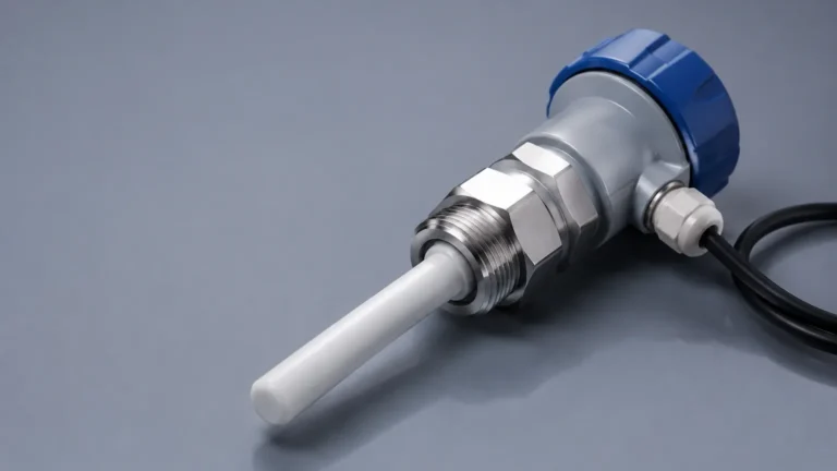
Tank Level Measurement
Tank Level Measurement
Tank level measurement is a fundamental requirement in industrial process control, inventory management, and safety systems. Whether managing bulk liquid storage, chemical processing, or wastewater treatment, the ability to accurately determine the volume or height of a substance within a vessel is critical for operational efficiency. Modern industrial environments utilize a variety of technologies to achieve this, ranging from simple mechanical indicators to advanced non-contact electronic sensors.
Selecting the appropriate technology for tank level measurement requires an understanding of the physical principles governing the measurement, the characteristics of the media being measured, and the environmental conditions of the installation site. This guide explores the primary measurement principles, selection criteria, and practical installation considerations for engineering professionals.
Understanding the Principles of Level Measurement
Level measurement technologies are generally categorized into two types: point level detection and continuous level measurement. Point level switches indicate when a material has reached a specific height (e.g., high-level or low-level alarms), while continuous sensors provide real-time data on the exact level throughout the entire range of the tank.
Time-of-Flight (ToF) Principle
This principle is used by radar and ultrasonic sensors. The device emits a signal (electromagnetic or sound wave) that travels to the surface of the material, reflects, and returns to the sensor. By measuring the time taken for the round trip and knowing the speed of the wave, the distance to the surface is calculated.
Hydrostatic Pressure Principle
Based on the physical law that the pressure at the bottom of a liquid column is proportional to the height of the liquid and its density ($P = \rho \cdot g \cdot h$). By measuring the pressure exerted by the liquid, the transmitter can determine the level, provided the density remains constant.
Buoyancy and Magnetic Principles
These methods use a float that moves with the liquid level. In magnetic level gauges, the float contains a magnet that interacts with external indicators or sensors to provide a visual or electronic representation of the level.
Non-Contact Technologies: Radar and Ultrasonic
Non-contact measurement is often preferred for corrosive, viscous, or abrasive materials because the sensor does not touch the media, reducing maintenance and extending the lifespan of the instrument.
Radar Level Meters
Radar technology is widely considered the gold standard for high-precision tank level measurement. It utilizes high-frequency electromagnetic waves (typically in the 26 GHz or 80 GHz range).
* FMCW Radar: Frequency Modulated Continuous Wave (FMCW) radar transmits a continuous signal with a changing frequency. The difference between the transmitted and received frequency is proportional to the distance. This method offers extreme accuracy (up to ±1 mm) and is highly resistant to interference from vapor, dust, or temperature fluctuations.
* Pulse Radar: This method sends short microwave pulses and measures the transit time. While slightly less precise than FMCW in some scenarios, it is highly effective for long-range measurements in large silos or tanks.
Ultrasonic Level Sensors
Ultrasonic sensors use high-frequency sound waves. They are cost-effective solutions for water treatment and simple liquid storage applications. However, they are sensitive to the medium's environment. Because sound requires a medium (air) to travel, changes in air temperature, pressure, or the presence of heavy foam and vapor can affect the speed of sound and, consequently, the accuracy of the measurement. Most modern ultrasonic units include integrated temperature compensation to mitigate these effects.
Contact Technologies: Hydrostatic and Magnetic
In applications where non-contact sensors may struggle—such as inside pressurized vessels or tanks with heavy foam—contact-based measurement remains a reliable choice.
Hydrostatic Level Transmitters
Hydrostatic sensors are submerged at the bottom of the tank or mounted via a flange. They are excellent for deep wells, vented tanks, and underground reservoirs. For pressurized tanks, a differential pressure (DP) transmitter is used to subtract the head pressure (the pressure of the gas above the liquid) from the total pressure at the bottom to isolate the liquid level.
Magnetic Level Gauges
Magnetic level gauges are installed on the side of a tank via a bypass chamber. As the liquid level in the tank rises or falls, the float in the chamber moves accordingly. This provides a clear visual indication for operators on the plant floor and can be equipped with reed switches or transmitters for remote monitoring. They are particularly favored in high-pressure steam applications and oil-gas separators.
Selection Guide for Tank Level Measurement
Choosing the right instrument involves balancing performance requirements with budget and environmental constraints. The following table provides a general comparison of common technologies.
| Technology | Accuracy | Media Type | Pressure Range | Temperature Range | Key Advantage |
| :— | :— | :— | :— | :— | :— |
| 80GHz Radar | ±1 mm | Liquids, Solids, Slurries | Up to 160 bar | -40°C to +250°C | Extremely precise; ignores internal obstructions. |
| Ultrasonic | ±0.25% FS | Water, Dilute Chemicals | Atmospheric | -40°C to +80°C | Low cost; easy to install in open vessels. |
| Hydrostatic | ±0.1% to 0.5% | Clear Liquids, Sludge | Dependent on sensor | -20°C to +100°C | Reliable for deep tanks and submersible use. |
| Magnetic Gauge | Visual/±5 mm | Clean Liquids, LPG | Up to 320 bar | -196°C to +450°C | No power required for visual; handles high pressure. |
| Level Switches | N/A (Point) | Almost all media | High | High | Reliable overfill protection and pump control. |
For a comprehensive overview of available instrumentation and technical specifications, engineers can visit the Main Page to review product options and application support.
Engineering Installation Considerations
Correct installation is as important as selecting the right technology. Even the most advanced radar sensor will fail if placed incorrectly.
1. Nozzle Height and Diameter: For radar and ultrasonic sensors, the nozzle should be as short as possible. If the nozzle is too long or narrow, the signal may reflect off the nozzle walls before reaching the media, creating a "false echo."
2. Dead Zones (Blocking Distance): Every ToF sensor has a minimum distance (dead zone) near the sensor face where it cannot measure. Ensure the maximum expected liquid level does not enter this zone.
3. Internal Obstructions: Agitators, heating coils, and ladders can reflect signals. While advanced software can "mask" these fixed echoes, it is best to install sensors in a location with a clear line of sight to the material surface.
4. Turbulence and Foam: Heavy turbulence can scatter signals, while thick foam can absorb ultrasonic and radar waves. In these cases, using a stilling well (a pipe installed inside the tank to provide a calm surface) is often necessary.
5. Mounting Position: Sensors should generally not be mounted in the center of a tank (to avoid multiple reflections from the tank walls) or too close to the wall (to avoid signal interference). A position at 1/4 to 1/6 of the tank diameter from the wall is often recommended.
Limitations and Environmental Factors
While modern instrumentation is robust, certain physical limitations must be acknowledged:
* Dielectric Constant ($ε_r$): Radar sensors rely on the dielectric constant of the material to reflect the signal. Materials with a very low dielectric constant (like certain oils or liquefied gases) reflect less energy, requiring high-sensitivity radar or guided wave radar (GWR).
* Vapor and Condensation: While radar is mostly unaffected by vapor, ultrasonic waves are significantly slowed by heavy steam or chemical vapors. Condensation on the sensor face can also cause signal attenuation. In such environments, radar with a PTFE drip-off antenna design is preferred.
* Density Variations: Hydrostatic measurement assumes a constant density. If the temperature of the liquid changes significantly, or if different liquids are mixed, the density will change, leading to errors in level calculation unless a compensation system is used.
Frequently Asked Questions (FAQ)
Q: Can I use an ultrasonic sensor on a vacuum tank?
A: No. Ultrasonic sensors require air or gas to transmit sound waves. In a vacuum, sound cannot travel. Radar is the appropriate choice for vacuum applications as electromagnetic waves do not require a medium.
Q: What is the difference between Guided Wave Radar (GWR) and Non-Contact Radar?
A: Non-contact radar sends waves through the air. GWR uses a probe (cable or rod) to guide the microwave signal directly to the media. GWR is superior for materials with very low dielectric constants or tanks with extreme turbulence and foam.
Q: How often do hydrostatic sensors need calibration?
A: This depends on the media. In clean water, they may remain accurate for years. In corrosive or scaling liquids, the diaphragm may become coated or degraded, requiring annual inspection and re-calibration.
Q: Is 80GHz radar always better than 26GHz radar?
A: 80GHz offers a narrower beam angle, which is better for avoiding internal obstructions and for use in small tanks. However, 26GHz radar may perform better in extremely dusty environments (like cement silos) because the longer wavelength can penetrate dust clouds more effectively.
Conclusion
Successful tank level measurement depends on a systematic evaluation of the process environment. By understanding the measurement principles—whether time-of-flight, pressure-based, or mechanical—and accounting for installation variables like tank geometry and media characteristics, engineers can ensure long-term reliability. For specific project requirements or custom OEM solutions, consulting with a professional manufacturer is recommended to match the technology to the application's unique demands.