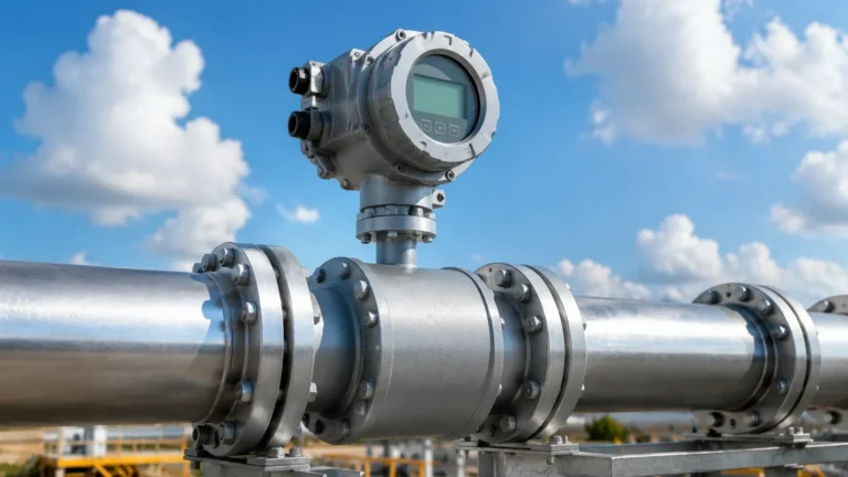
Vega Checkout
Vega Checkout
In the landscape of industrial automation, the term "checkout" refers to the rigorous process of verifying that instrumentation meets the specific demands of a process before, during, and after installation. For engineers and procurement specialists, a "Vega checkout"—or the systematic evaluation of high-precision level measurement devices—is a critical phase in ensuring plant safety and operational efficiency. Whether you are integrating radar, ultrasonic, or hydrostatic sensors, understanding the underlying physics and the verification requirements is essential for a successful deployment.
Level measurement is not a one-size-fits-all solution. The transition from a theoretical design on a P&ID (Piping and Instrumentation Diagram) to a functional instrument in the field requires a deep dive into measurement principles and a strict adherence to commissioning protocols. This guide outlines the technical foundations and the practical steps necessary to perform a comprehensive checkout of industrial level instruments.
Fundamental Measurement Principles
Before proceeding with an instrument checkout, it is vital to understand how different technologies interact with the process media. Each method has distinct advantages and physical limitations that influence the verification process.
Radar Level Measurement (ToF)
Radar sensors, particularly those operating in the 80 GHz frequency range, utilize the Time-of-Flight (ToF) principle. The sensor emits a high-frequency microwave signal toward the medium. This signal reflects off the surface and returns to the antenna. The instrument calculates the distance based on the time elapsed between emission and reception.
* Non-Contact Radar: Ideal for corrosive or high-temperature liquids. Since the sensor does not touch the media, it is less prone to wear. During checkout, verifying the "blocking distance" (the area near the antenna where measurement is impossible) is a priority.
* Guided Wave Radar (GWR): Uses a probe (cable or rod) to guide the microwave signal. This is highly effective for low dielectric constants or turbulent surfaces. The checkout process here must include a physical inspection of the probe for any potential contact with tank internals.
Ultrasonic Level Sensors
Ultrasonic devices emit sound pulses that bounce off the surface of the liquid or solid. While cost-effective for water treatment and simple storage applications, they are sensitive to air temperature, pressure, and vapor layers. Because the speed of sound varies with temperature, these sensors usually require an integrated temperature probe for compensation.
Hydrostatic Pressure Measurement
This principle relies on the relationship between the height of a liquid column and the pressure it exerts at the base. The formula $P = \rho \cdot g \cdot h$ (where $P$ is pressure, $\rho$ is density, $g$ is gravity, and $h$ is height) governs the measurement. A checkout for hydrostatic transmitters must confirm the exact density of the fluid, as any deviation will result in a linear error in level calculation.
The Checkout Process: Step-by-Step Verification
A professional checkout ensures that the hardware delivered matches the application's technical requirements. This process is often divided into the "bench check" and the "field loop check."
1. Specification Alignment
The first step in any checkout is comparing the physical device nameplate against the process data sheet. Key parameters to verify include:
* Pressure Rating: Ensure the flange or thread rating exceeds the maximum possible process pressure (e.g., a 10 bar / 145 psi rating for a 6 bar process).
* Material Compatibility: Verify that wetted parts (316L stainless steel, PTFE, Hastelloy) are resistant to the process media.
* Output Signal: Confirm the device is configured for the correct protocol, such as 4-20mA HART, Profibus, or Foundation Fieldbus.
2. Bench Configuration
Before the sensor is mounted on the tank, it should be powered up in a controlled environment. Using a HART communicator or manufacturer-specific software, engineers set the "Zero" (4mA) and "Span" (20mA) points. For a radar sensor, this involves inputting the tank height and the desired measurement range.
3. Echo Curve Analysis
For radar and ultrasonic technologies, the most critical part of a checkout is the echo curve analysis. This visual representation shows the strength of the return signal. A clean "peak" should represent the product surface, while smaller peaks might indicate false reflections from agitators or ladders. Modern instruments allow for "false signal suppression," where the software is taught to ignore these static reflections.
Practical Selection Criteria
Choosing the right technology is the precursor to a successful checkout. The following table provides a reference for matching technology to common industrial scenarios.
| Application Scenario | Recommended Technology | Primary Checkout Concern |
| :— | :— | :— |
| Corrosive Chemical Storage | Non-contact Radar (PTFE Wetted) | Material integrity & flange sealing |
| Wastewater Open Channel | Ultrasonic | Temperature compensation accuracy |
| High-Pressure Steam Boiler | Guided Wave Radar | Steam compensation & bypass pipe alignment |
| Deep Well/Borehole | Hydrostatic (Submersible) | Cable venting & density calibration |
| Food & Beverage (Hygienic) | Radar or Hydrostatic | Surface finish (Ra < 0.8 \mu m) & CIP resistance |
| Solid Grain Silo | High-frequency Radar | Dust penetration & angle of repose |
Installation Considerations and Best Practices
Even the best-calibrated instrument will fail if the installation is flawed. During the field checkout, the following physical factors must be inspected:
Nozzle Geometry
The mounting nozzle should be as short and wide as possible. For radar sensors, if the nozzle is too narrow or long, the microwave signal may reflect off the nozzle walls before reaching the tank, creating a "ringing" effect that obscures the true level. A common rule of thumb is that the nozzle height should not exceed its diameter by more than a factor of 2:1 for standard applications.
Avoiding Obstructions
The "beam angle" of the sensor must be considered. For a typical 80 GHz radar, the beam angle might be as narrow as 3 degrees. For an ultrasonic sensor, it could be 10 degrees or more. The checkout must ensure that the signal path is clear of:
* Inlet pipes and falling product.
* Heating coils.
* Ladders and structural supports.
* Agitator blades (unless using synchronized filtering).
Environmental Protection
For outdoor installations, sunshades are recommended to prevent electronic overheating and to reduce temperature fluctuations that can affect ultrasonic speed-of-sound calculations. Ensure that cable glands are pointing downward to prevent moisture ingress into the housing, which is a leading cause of instrument failure during the first year of operation.

Limitations and Common Risks
No measurement technology is infallible. Recognizing the limitations during the checkout phase prevents costly downtime later.
1. Foam Interference: Heavy, thick foam can absorb radar and ultrasonic signals, leading to a "loss of echo." In such cases, a magnetic level gauge or a hydrostatic transmitter might be a more reliable secondary measurement.
2. Vacuum Conditions: Ultrasonic sensors cannot operate in a vacuum because sound requires a medium (air/gas) to travel. Radar, being an electromagnetic wave, is unaffected by vacuum.
3. Build-up and Coating: In sticky media, material can build up on the sensor face or probe. While some radar sensors can "see through" thin coatings, significant build-up will eventually cause signal attenuation. Checkout procedures should include a maintenance schedule for cleaning if build-up is anticipated.
4. Dielectric Constant (dk): Radar relies on a change in the dielectric constant at the air-liquid interface. If the liquid has a very low dk (like some hydrocarbons), the reflection will be weak. GWR is often preferred for low-dk fluids because it concentrates the signal energy.
Frequently Asked Questions (FAQ)
Q: How often should I perform a checkout on my level instruments?
A: A full checkout is mandatory during initial commissioning. Subsequently, an annual verification or "proof test" is recommended, especially in safety-instrumented systems (SIS). If the process media or operating temperature changes significantly, a re-checkout is necessary.
Q: Can I use a radar sensor in a tank with an agitator?
A: Yes. During the checkout, you can use "echo masking" or "gate tracking" to ignore the intermittent signals caused by the moving blades. However, the sensor should be mounted as far from the agitator shaft as possible.
Q: What is the difference between accuracy and repeatability in these checkouts?
A: Accuracy is how close the reading is to the actual physical level. Repeatability is the instrument's ability to provide the same reading under identical conditions. In many B2B process control applications, high repeatability is often more critical than absolute accuracy for maintaining consistent product quality.
Q: Why is my hydrostatic transmitter reading incorrectly after a fluid change?
A: Hydrostatic pressure is density-dependent. If you switch from water (density 1.0) to an oil (density 0.8), the pressure at the bottom of the tank will be lower for the same height of liquid. You must update the density parameter in the transmitter during your checkout.
Conclusion
A thorough checkout is the bridge between purchasing a high-quality instrument and achieving reliable process control. By understanding the physics of radar, ultrasonic, and hydrostatic measurement, and by following a disciplined verification protocol, engineering teams can mitigate risks and ensure long-term performance. For professionals seeking high-performance hardware to complement their checkout procedures, Welk offers a robust range of industrial solutions. You can explore our extensive catalog of radar, ultrasonic, and hydrostatic sensors on our Main Page, where we provide technical specifications and application support to help you select the right tool for your specific industrial challenges.
Finalizing the checkout process involves documenting all settings, saving the echo curves, and ensuring the local display matches the control room readings. With these steps completed, the instrument is ready to serve as a reliable component of your industrial automation infrastructure.