Capacitance vs Radar Level Transmitter
Capacitance vs Radar Level Transmitter: A Technical Engineering Comparison
In the field of industrial process automation, selecting the correct level measurement technology is critical for operational safety, efficiency, and cost control. Two of the most prevalent technologies used across the water treatment, chemical, and oil and gas sectors are capacitance and radar. While both serve the purpose of continuous level monitoring, they operate on fundamentally different physical principles. This guide provides a detailed technical analysis of the capacitance vs radar level transmitter debate, helping engineers and procurement specialists determine the optimal solution for their specific application.
Understanding Measurement Principles
Before evaluating selection criteria, it is essential to understand the physics governing each instrument.
Capacitance Level Measurement
Capacitance level transmitters operate based on the electrical properties of a capacitor. In an industrial tank, the sensor probe acts as one plate of the capacitor, and the vessel wall (if metallic) acts as the second plate. If the tank is non-conductive, a reference ground rod is used. These two "plates" are separated by the process medium, which acts as the dielectric material.
The capacitance ($C$) is determined by the formula:
$$C = \epsilon \cdot \frac{A}{d}$$
Where:
* $\epsilon$ is the dielectric constant (permittivity) of the material between the plates.
* $A$ is the surface area of the plates.
* $d$ is the distance between the plates.
As the liquid or solid level rises, it displaces the air (which has a dielectric constant of approximately 1) with the process material (which has a higher dielectric constant). This change in the overall dielectric property of the medium between the probe and the wall results in a proportional change in capacitance, which the electronics convert into a level signal. This technology requires direct contact with the medium.
Radar Level Measurement
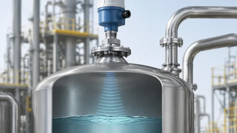
Radar Level Meters utilize electromagnetic waves, typically in the microwave range (6 GHz to 80 GHz), to measure distance. There are two primary types of radar technology: Pulse Radar and Frequency Modulated Continuous Wave (FMCW).
1. Pulse Radar: The sensor emits a microwave pulse that travels to the surface of the medium, reflects, and returns to the sensor. The instrument measures the "Time of Flight" (ToF). Since the speed of light is constant, the distance is calculated as: $Distance = \frac{Speed \times Time}{2}$.
2. FMCW Radar: The sensor emits a continuous signal with a constantly changing frequency. The difference in frequency between the emitted signal and the reflected signal is proportional to the distance.
Unlike capacitance, radar is a non-contact technology (in the case of free-space radar). It is largely independent of the dielectric constant, provided the value is high enough to reflect the signal back to the antenna.
Detailed Comparison: Capacitance vs Radar Level Transmitter
When comparing a capacitance vs radar level transmitter, several operational factors must be weighed to ensure long-term reliability.
1. Accuracy and Sensitivity
Radar technology generally offers superior accuracy, often within $\pm$1 mm to $\pm$3 mm. Because it relies on the speed of light, it is not affected by changes in the density or temperature of the medium.
Capacitance transmitters are sensitive to any change in the dielectric constant ($\epsilon$) of the material. If the moisture content in a solid changes, or if a liquid's chemical composition fluctuates, the dielectric constant shifts, leading to measurement errors. Consequently, capacitance is often better suited for applications where the medium is consistent.
2. Media Characteristics and Coating
A significant limitation of capacitance probes is their susceptibility to "build-up" or coating. If a conductive liquid leaves a film on the probe, the instrument may continue to read a high level even after the tank has been emptied. While some advanced capacitance units feature "active shield" technology to ignore coating, it remains a point of concern.
Radar level meters are non-contact, meaning they are immune to the corrosive or viscous nature of the liquid. They are ideal for aggressive chemicals or slurries that would otherwise degrade or coat a contact-based capacitance probe.
3. Process Conditions (Temperature and Pressure)
Capacitance probes are robust and can be engineered to withstand extreme temperatures (up to 400°C or more) and very high pressures (up to 500 bar). Because the probe is a solid rod or cable, it is physically resilient.
Radar transmitters also handle high temperatures and pressures, but the electronics and antenna materials (such as PTFE or ceramics) must be carefully selected. High-frequency radar (80 GHz) is particularly effective in avoiding interference from internal tank obstructions, which can be a challenge in high-pressure reactors.
Selection Matrix for Industrial Applications
The following table summarizes the performance of both technologies across common industrial parameters:
| Feature | Capacitance Transmitter | Radar Level Meter |
| :— | :— | :— |
| Measurement Type | Contact | Non-contact (Free-space) |
| Accuracy | Moderate ($\pm$0.5% to 1%) | High ($\pm$1mm to 10mm) |
| Dielectric Sensitivity | High (Requires constant $\epsilon$) | Low (Requires minimum $\epsilon$ > 1.4) |
| Impact of Foam | Significant | Depends on foam density/type |
| Impact of Dust/Vapor | Minimal | Minimal (especially at lower GHz) |
| Maintenance | Higher (due to probe cleaning) | Very Low |
| Cost | Lower Initial Investment | Higher Initial Investment |
| Installation | Top-down (Probe length limited) | Top-down (Flexible) |
Installation Considerations
For Capacitance Transmitters:
* Grounding: Ensure the tank is properly grounded. In non-metallic tanks, a dual-probe system or a ground tube is mandatory.
* Proximity to Walls: The probe must be installed at a fixed distance from the wall to maintain a consistent capacitance field. Avoid placing it too close to the inlet where the flow might cause the probe to bend or vibrate.
* Calibration: These units almost always require a two-point calibration (empty and full) with the actual process material in the tank.
For Radar Level Meters:
* Nozzle Geometry: The radar beam must have a clear path to the liquid surface. Avoid installing the unit too close to the tank wall to prevent false reflections (the "ringing" effect).
* Obstructions: Internal structures like agitators, heating coils, or ladders can reflect radar signals. Modern radar units use "False Echo Suppression" software to map out these static reflections.
* Beam Angle: Higher frequency radar (e.g., 80 GHz) has a narrower beam angle, making it easier to install in narrow tanks or tanks with many internal obstructions.
Limitations and Risks
Capacitance Limitations:
* Dielectric Shifting: Not suitable for tanks where different products are stored interchangeably unless recalibrated each time.
* Conductive Coating: Conductive build-up on the probe can cause a permanent "short circuit" in the measurement logic.
* Length Constraints: For very deep silos (over 20 meters), the weight of a cable probe and the tension caused by solids can lead to mechanical failure.
Radar Limitations:
* Low Dielectric Materials: Extremely low dielectric materials (like certain liquefied gases) may not reflect enough energy for a standard radar. In these cases, Guided Wave Radar (GWR) is often used.
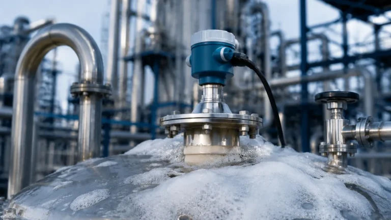
* Heavy Foam: Dense, thick foam can absorb radar signals, leading to a "loss of echo." While some frequencies penetrate foam better than others, it remains a challenging environment for non-contact radar.
Industrial Application Examples
* Water Treatment: Radar is preferred for open channel flow and large storage tanks due to its non-contact nature and ease of installation over basins. Capacitance is sometimes used in chemical feed tanks where the liquid is consistent and the tank is small.
* Chemical Processing: In highly corrosive acid tanks, a PTFE-coated radar is often the standard to avoid probe degradation. However, for interface measurement (e.g., oil sitting on top of water), capacitance probes are highly effective because they can detect the change in dielectric constant between the two liquids.
* Oil and Gas: Radar is the industry standard for custody transfer and high-accuracy storage tank gauging. Capacitance is frequently used for fuel/water separation interface detection in separators.
Buyer’s Checklist: Information to Confirm Before Purchase
When sourcing equipment from an international manufacturer like Welk, providing accurate process data is vital for a successful installation. Ensure you have the following information ready:
1. Medium Properties: What is the dielectric constant? Is the material corrosive, viscous, or prone to crystallization?
2. Vessel Specifications: What is the tank height and diameter? What is the material of construction (metal, plastic, concrete)?
3. Process Conditions: What are the maximum and minimum operating temperatures and pressures?
4. Mounting Requirements: What is the size and height of the mounting nozzle? Are there internal obstructions like agitators?
5. Output Requirements: Do you require 4-20mA, HART, Modbus, or Profibus communication?
6. Safety Certifications: Do you require ATEX, IECEx, or SIL2 ratings for hazardous areas?
Frequently Asked Questions (FAQs)
Q: Can a radar level meter measure solids?
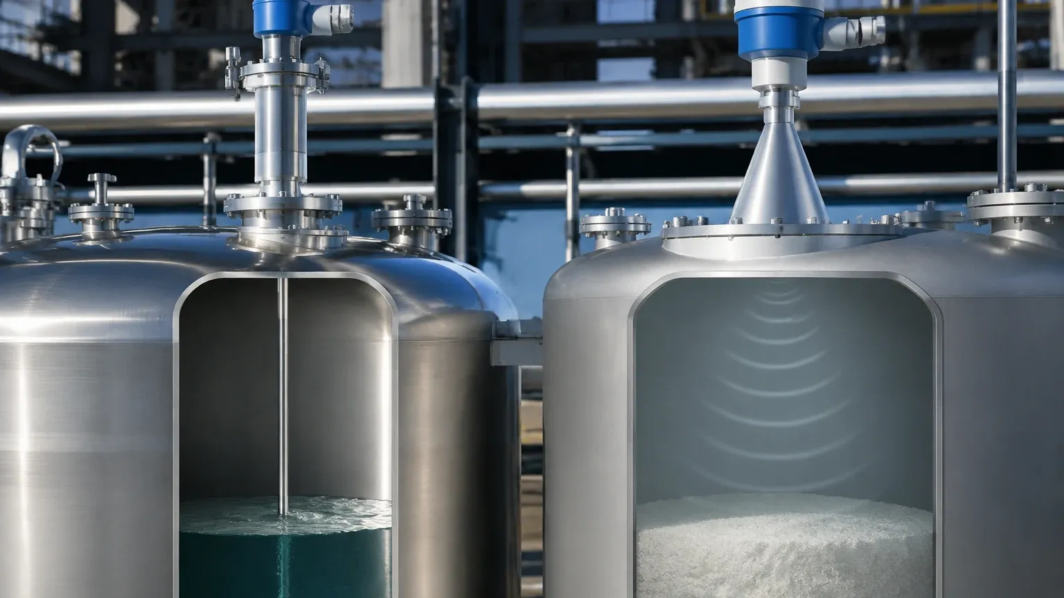
A: Yes. However, for solids, it is recommended to use a radar with a high frequency (76-80 GHz) and a dust-resistant lens antenna, as the angle of repose in solids can scatter signals.
Q: Does capacitance work in plastic tanks?
A: Yes, but you must use a probe with an integrated ground reference (a concentric shield or a second rod), as the plastic wall cannot act as a ground plane.
Q: Is radar affected by vacuum conditions?
A: No. Radar waves do not require a medium to travel (unlike ultrasonic waves), making them ideal for vacuum reactors.
Q: When is capacitance better than radar?
A: Capacitance is often superior for interface measurement (detecting the line between two different liquids) and in applications where the budget is limited and the process medium is chemically stable and non-coating.
Conclusion
The choice between a capacitance vs radar level transmitter depends on the specific demands of the process environment. While capacitance offers a robust and cost-effective solution for stable media and interface detection, Radar Level Meters provide the high precision and low-maintenance benefits required for complex, aggressive, or high-accuracy industrial applications. By understanding the dielectric properties of your media and the physical constraints of your vessel, you can select the technology that ensures the highest level of operational reliability.