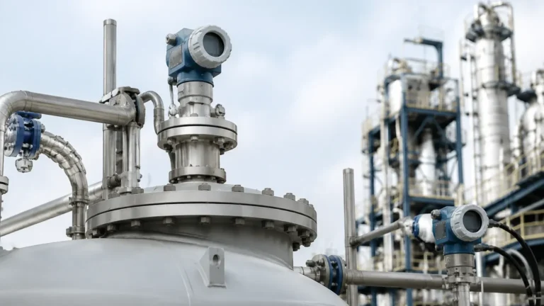
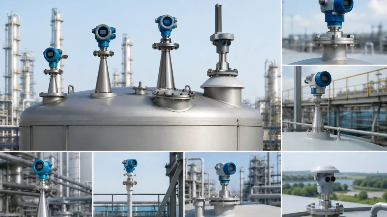
Radar Level Transmitter Drawing
Radar Level Transmitter Drawing: A Comprehensive Engineering Guide to Design and Installation
In the field of industrial process automation, the accuracy of level measurement is fundamental to safety, efficiency, and inventory management. Among the various technologies available, Radar Level Meters have emerged as a preferred solution for both liquid and solid applications due to their non-contact nature and high precision. However, the successful implementation of these instruments depends heavily on the initial engineering phase, where the radar level transmitter drawing serves as the primary technical reference for mechanical fit, electrical integration, and signal optimization.
This guide explores the technical intricacies of radar level measurement, the essential components of a transmitter drawing, and the practical considerations engineers must address to ensure reliable performance in demanding industrial environments.
1. Fundamental Principles of Radar Level Measurement
Before analyzing a technical drawing, it is essential to understand how radar technology interacts with the process media. Radar level transmitters operate by emitting high-frequency electromagnetic waves (microwaves) toward the surface of the material being measured. These waves reflect off the surface and return to the sensor antenna.
Time-of-Flight (ToF) and FMCW
Most modern industrial radar transmitters utilize one of two primary measurement principles:
1. Pulse Radar: The instrument sends out a short microwave pulse and measures the time it takes for the pulse to travel to the surface and back. The distance is calculated using the formula: $Distance = (C \times t) / 2$, where $C$ is the speed of light and $t$ is the transit time.
2. Frequency Modulated Continuous Wave (FMCW): The transmitter emits a continuous signal with a constantly changing frequency. The difference in frequency between the emitted signal and the reflected signal is proportional to the distance. FMCW is generally preferred for high-precision applications due to its superior signal-to-noise ratio.
Frequency and Beam Angle
The frequency of the radar (typically 6GHz, 26GHz, or 80GHz) determines the beam angle. A higher frequency, such as 80GHz, allows for a much narrower beam, which is critical for avoiding internal tank obstructions like agitators, heating coils, or ladders. When reviewing a radar level transmitter drawing, the beam angle is a vital metric for calculating the "keep-out zone" within the vessel.
2. Deciphering the Radar Level Transmitter Drawing
A professional engineering drawing for a radar level transmitter is not merely a physical representation; it is a multi-layered document providing dimensional, electrical, and installation data. For international procurement and site engineering, these drawings usually consist of three main sections.
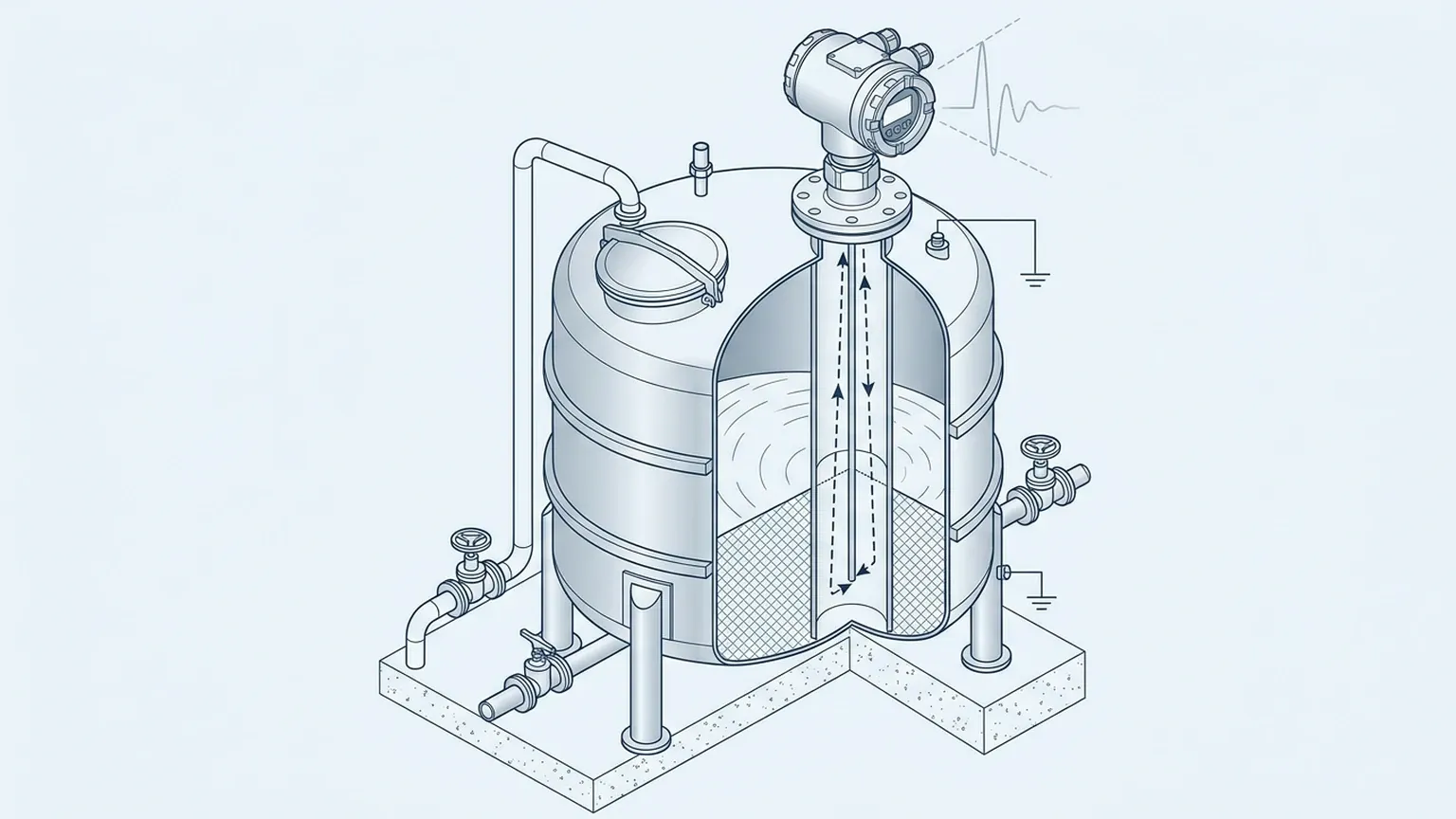
Dimensional and Mechanical Outline
This section defines the physical footprint of the device. Key elements include:
* Overall Height and Width: Critical for ensuring the transmitter fits within the available headspace above a tank.
* Process Connection Details: Specifies whether the unit uses a threaded connection (e.g., G1½, 1½ NPT) or a flange (e.g., DN80, ANSI 3").
* Antenna Type and Length: The drawing must show the antenna extension. In many cases, the antenna must extend beyond the mounting nozzle to prevent signal interference from the nozzle neck.
* Housing Orientation: Details regarding the electronics enclosure, including the position of the cable entries (usually M20x1.5 or ½ NPT).
Electrical Wiring and Loop Diagrams
The electrical portion of the drawing illustrates how the device integrates into the plant's control system. Most industrial Radar Level Meters are 2-wire loop-powered devices (4-20mA with HART protocol), though 4-wire versions exist for high-power requirements or integrated heating elements.
* Terminal Assignments: Clearly labeling positive, negative, and ground terminals.
* Shielding Requirements: Guidance on cable shielding to prevent Electromagnetic Interference (EMI).
Installation Constraints and Beam Path
Advanced drawings include a "field of view" or beam spread diagram. This illustrates the cone-shaped path of the radar signal. Engineers use this to ensure that no structural members of the tank intersect with the signal path, which would otherwise cause "false echoes."
3. Technical Selection Criteria
Choosing the right radar transmitter requires a balance between process conditions and instrument capabilities. The following table provides a comparison of common radar configurations used in B2B industrial applications.
| Feature | 26GHz Pulse Radar | 80GHz FMCW Radar | Guided Wave Radar (GWR) |
| :— | :— | :— | :— |
| Measurement Range | Up to 30m | Up to 120m | Up to 75m |
| Beam Angle | 8° to 20° | 3° to 8° | N/A (Contacting) |
| Accuracy | ±3mm to ±5mm | ±1mm | ±2mm |
| Pressure Limit | Up to 40 bar | Up to 160 bar | Up to 400 bar |
| Best Use Case | Large tanks, simple liquids | Narrow vessels, high precision | Low DK fluids, foam, bypass pipes |
| Dielectric Constant (εr)| > 1.9 | > 1.4 | > 1.2 |
4. Engineering Installation Guidelines
The accuracy of a radar level transmitter is highly dependent on its physical placement. When translating a radar level transmitter drawing to a field installation, follow these authoritative guidelines:
Positioning Relative to Tank Geometry
* Avoid the Center: Do not install the transmitter in the exact center of a domed or cylindrical tank. This can lead to multiple reflections that amplify noise.
* Distance from Wall: Maintain a minimum distance from the tank wall, typically 1/10th of the tank height or at least 200mm, to prevent signal attenuation.
* Nozzle Height: The mounting nozzle should be as short as possible. If the nozzle is long, the antenna must be extended (using an extension rod) so that the emitter tip is at least 10mm below the bottom of the nozzle.
Interference Management
* Inflow Streams: Never install the radar where the filling stream will intersect the microwave beam. This causes extreme turbulence and signal loss.
* Internal Obstructions: If an agitator or ladder is in the beam path, the transmitter's software must be configured with a "False Echo Suppression" or "Empty Tank Mapping" to ignore these static reflections.
Environmental Protection
* Sunshade: For outdoor installations in high-temperature regions, a sunshade is recommended to prevent the electronics from overheating and to reduce condensation within the housing.
* Drip Loop: Always install a drip loop in the electrical conduit to prevent moisture from entering the cable glands.
5. Limitations and Application Risks
While radar is highly versatile, it is not a universal solution. Engineers must be aware of the following physical limitations:
1. Low Dielectric Constant (εr): Materials with a very low dielectric constant (e.g., liquefied gases, certain oils) do not reflect radar waves well. In these cases, a Guided Wave Radar (GWR) or a high-sensitivity 80GHz FMCW unit with a large flange antenna is required.
2. Heavy Foam: Dense, thick foam can absorb the radar signal entirely, leading to a "Loss of Echo" (LOE) error. If foam is constant, a low-frequency radar (6GHz) or a mechanical float-type gauge may be more reliable.
3. Vapor and Condensation: While radar can penetrate most vapors, extreme steam or heavy condensation on the antenna lens can attenuate the signal. For these environments, antennas with PTFE or PEEK covers (lens antennas) are used to shed droplets.
6. Frequently Asked Questions (FAQ)
Q: How do I determine the correct beam angle for my tank?
A: The beam angle is provided in the manufacturer's data sheet and the radar level transmitter drawing. You can calculate the beam diameter ($D$) at any depth ($H$) using the formula: $D = 2 \times H \times \tan(Angle / 2)$. Ensure this diameter is smaller than the clearance between the nozzle and the nearest obstruction.
Q: Can I use a radar transmitter on a plastic tank?
A: Yes. Microwaves can pass through plastic (non-conductive) materials. It is possible to mount a radar transmitter above a plastic tank and measure the level through the top of the vessel, provided the plastic is not carbon-filled or metallic-lined.
Q: What is the significance of the "Dead Zone" (Blocking Distance)?
A: The dead zone is the area immediately below the antenna where measurement is not possible. This is typically between 50mm and 200mm depending on the model. Ensure your maximum fill level does not enter this zone to avoid erratic readings.
Q: Why is 80GHz becoming the industry standard?
A: 80GHz technology offers a much smaller antenna size for the same beam angle compared to 26GHz. This allows for easier installation on small nozzles and provides higher resolution, which is essential for measuring through narrow openings or in tanks with complex internals.
7. Summary for International Buyers
When requesting a quote or reviewing a technical submittal for Radar Level Meters, ensure the following information is confirmed against the provided radar level transmitter drawing:
1. Material Compatibility: Ensure the wetted parts (e.g., 316L Stainless Steel, PTFE) are compatible with the process media.
2. Certification: Verify that the drawing indicates the necessary hazardous area certifications (ATEX, IECEx, or SIL2/3) required for your site.
3. Process Connection: Double-check flange ratings (e.g., PN16 vs. PN40) to ensure mechanical compatibility with existing tank nozzles.
By meticulously reviewing the technical drawings and adhering to established installation principles, engineering teams can maximize the reliability and lifespan of their level measurement instrumentation, ensuring long-term operational success in any industrial environment.