Thermal Mass Flowmeter
Thermal Mass Flowmeter
In the landscape of industrial process control, measuring gas flow accurately is essential for energy management, safety, and process optimization. The thermal mass flowmeter has emerged as a preferred technology for gas applications because it measures mass flow directly without the need for additional pressure or temperature compensation. Unlike volumetric flowmeters, which require complex calculations to determine the actual amount of gas moving through a pipe, thermal mass instruments leverage the physical properties of the gas to provide a highly precise reading of the molecular flow.
For engineers and facility managers looking to integrate these instruments into a broader automation strategy, understanding the underlying physics and selection criteria is paramount. This guide provides a technical deep dive into thermal mass flowmeter technology, its practical applications, and how it complements other industrial sensors found on the Main Page of professional instrumentation providers.
Measurement Principles of Thermal Mass Flowmeters
Thermal mass flowmeters operate based on the principle of thermal dispersion or "King’s Law." The technology relies on the fact that a moving fluid (typically a gas) will absorb heat from a heated surface in proportion to its mass flow rate. In a standard industrial thermal mass flowmeter, the sensor probe consists of two Resistance Temperature Detectors (RTDs).
The Two-Sensor Method
1. Reference Sensor: This RTD measures the actual temperature of the process gas. It provides a baseline to ensure the instrument accounts for fluctuations in the ambient process temperature.
2. Heated Sensor (Active Sensor): This RTD is heated to a specific temperature above the reference sensor. As gas flows past this sensor, the gas molecules carry heat away from the probe.
Operational Modes
There are two primary methods used by manufacturers like Welk to translate this heat loss into a flow reading:
* Constant Temperature Differential: In this mode, the electronics provide variable power to the heated sensor to maintain a constant temperature difference (ΔT) between the heated sensor and the reference sensor. As the mass flow increases, more power is required to maintain the ΔT. This power consumption is directly proportional to the mass flow rate of the gas.
* Constant Power: Here, a fixed amount of power is supplied to the heated sensor. The temperature difference between the two sensors is measured. As flow increases, the temperature of the heated sensor drops because of the cooling effect of the gas. The resulting change in ΔT is used to calculate the flow.
Because the cooling effect is dependent on the number of gas molecules passing the sensor (the mass) and the specific heat of the gas, the measurement is inherently a mass flow reading. This eliminates the need for external computers to calculate "Standard Cubic Meters" from "Actual Cubic Meters."
Key Components and Construction
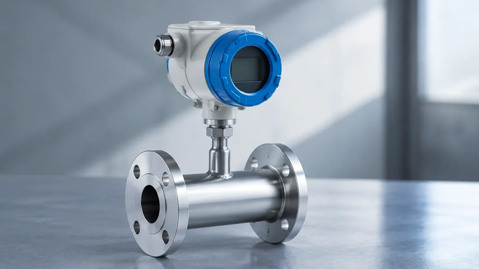
A thermal mass flowmeter is generally comprised of three main parts: the sensor elements, the probe or body, and the transmitter electronics.
Sensor Elements
The RTDs are typically constructed from platinum wire wound around a ceramic mandrel or deposited as a thin film on a substrate. To withstand harsh industrial environments, these sensors are encased in protective metal sheaths, often made of 316L Stainless Steel, Hastelloy, or Monel. The choice of material is critical for chemical compatibility, especially in corrosive applications like wastewater treatment or chemical processing.
The Transmitter
The transmitter contains the microprocessor and signal conditioning electronics. Modern units provide various outputs, including 4-20mA, pulse, and digital protocols like Modbus or HART. Many industrial models also feature local displays that show both the instantaneous flow rate and the totalized flow.
In-line vs. Insertion Thermal Mass Flowmeters
Choosing the correct physical configuration is the first step in a successful installation. Thermal mass flowmeters are categorized into two primary types based on how they interface with the piping system.
In-line Flowmeters
In-line models consist of a flow body that is flanged or threaded directly into the pipe. These are typically used for smaller pipe diameters, generally from DN15 to DN100 (1/2" to 4"). The advantage of an in-line meter is that the sensor is factory-calibrated within a known pipe section, which minimizes flow profile errors.
Insertion Flowmeters
Insertion models feature a long probe that is inserted into the pipe through a compression fitting or a flange. These are ideal for larger pipe diameters (DN100 and above) and offer a cost-effective solution for large-scale ducting. They can often be installed via a "hot tap" method, allowing for installation or removal without shutting down the process gas flow.
Selection Criteria and Technical Specifications
When selecting a thermal mass flowmeter, engineers must evaluate several variables to ensure long-term accuracy and reliability. The following table outlines the primary considerations for common industrial gases.
| Gas Type | Typical Application | Key Selection Factor |
| :— | :— | :— |
| Compressed Air | Leak detection, cost allocation | Low-pressure drop, high sensitivity to low flow. |
| Natural Gas | Burner control, billing | Explosion-proof (ATEX/IECEx) certifications. |
| Biogas | Digester monitoring | Corrosion resistance (H2S) and moisture handling. |
| Nitrogen | Tank blanketing | Precision at very low velocities. |
| Carbon Dioxide | Food & Beverage carbonation | Specific heat calibration for pure CO2. |
| Oxygen | Aeration, medical gas | Oxygen cleaning of all wetted parts. |
Technical Parameters to Confirm
* Flow Range (Turndown Ratio): Thermal mass flowmeters offer exceptional turndown ratios, often 100:1 or higher. This allows for accurate measurement from very low velocities (0.1 m/s) up to high-speed flows (60 m/s or more).
* Process Temperature: Standard probes typically handle up to 150°C, though high-temperature versions can reach 400°C.
* Process Pressure: While the measurement principle is independent of pressure, the physical construction of the probe must be rated for the maximum system pressure, often up to 40 bar or 63 bar.
* Gas Composition: Since the meter is calibrated for a specific gas (based on its thermal conductivity and specific heat), any change in gas composition will result in measurement errors.
Installation Guidelines for Optimal Accuracy
Even the most advanced thermal mass flowmeter will provide inaccurate data if installed incorrectly. The goal of installation is to provide the sensor with a "fully developed flow profile."
Straight Pipe Run Requirements
To avoid turbulence caused by elbows, valves, or reducers, specific straight-run distances are required:
* Upstream: Minimum 10 to 20 pipe diameters (D) of straight pipe.
* Downstream: Minimum 5 pipe diameters (D) of straight pipe.
If the installation site lacks the necessary space, flow conditioners (perforated plates) can be used to artificially stabilize the flow profile.
Orientation and Moisture
Moisture is the primary enemy of thermal mass technology. If water droplets hit the heated sensor, the instrument will interpret the energy required to evaporate the droplet as a massive spike in gas flow. To mitigate this:
* Install the meter in a horizontal pipe section.
* Position the probe at a 45-degree angle or from the top to prevent condensate from pooling on the sensor.
* Ensure the gas is dry or install a water trap upstream of the meter.
Limitations and Application Risks
While highly versatile, the thermal mass flowmeter is not a universal solution for every fluid. Understanding its boundaries prevents costly specification errors.
1. Liquid Contamination: As mentioned, liquid droplets cause significant measurement errors. This technology is strictly for gases.
2. Coating and Buildup: If the process gas is "dirty" (e.g., contains oils or tars), a coating can form on the sensor. This acts as an insulator, slowing the heat transfer and causing the meter to read lower than the actual flow. Regular cleaning or the use of self-cleaning sensor designs is necessary in these environments.
3. Changing Gas Mixtures: If a meter is calibrated for 100% Nitrogen but is used for a mixture of 80% Nitrogen and 20% CO2, the reading will be inaccurate because the thermal properties of the mixture differ from the calibration gas.
4. High Velocity Limits: At very high velocities, the cooling effect plateaus, and the meter may lose sensitivity.
Frequently Asked Questions (FAQs)
Q: Does a thermal mass flowmeter require annual calibration?
A: While the electronics are very stable, the physical sensor can be affected by the process environment. In regulated industries or for billing purposes, annual calibration is recommended. For general process monitoring, a field check or "zero-flow" validation may suffice.
Q: Can I use one meter for different types of gases?
A: Most thermal mass flowmeters are calibrated for a specific gas or a specific mixture. Some high-end transmitters allow the user to select from a library of pre-programmed gases, but for maximum accuracy, factory calibration for the specific gas is preferred.
Q: How does it compare to a Vortex flowmeter?
A: Vortex meters are excellent for high-velocity steam and gas but have a "low-flow cutoff" where they cannot measure anything. Thermal mass flowmeters excel at the low end of the flow range, making them superior for leak detection and low-pressure gas monitoring.
Q: What is the pressure drop across the meter?
A: One of the main benefits of this technology is the negligible pressure drop. Insertion meters have almost zero impact on system pressure, while in-line meters have a very low drop compared to orifice plates or Venturi tubes.
Conclusion and Next Steps
The thermal mass flowmeter is a cornerstone of modern industrial gas measurement, offering direct mass flow readings, high sensitivity, and no moving parts. When integrated correctly, it provides the data necessary for optimizing combustion, reducing waste in compressed air systems, and ensuring environmental compliance in emissions monitoring.
For engineers designing complete process control loops, flow measurement is often paired with level measurement in tanks and vessels. Whether you are monitoring the level of fuel in a storage tank or the flow of gas to a burner, selecting the right instrument requires a balance of technical knowledge and application experience. To explore a full range of industrial measurement solutions, including radar, ultrasonic, and hydrostatic sensors, visit the Main Page to review product options and application support. Ensuring that both your flow and level instruments are calibrated for your specific process conditions is the most effective way to guarantee long-term operational efficiency.