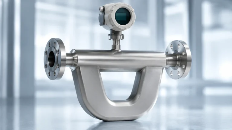
Micropilot Fmr51
Micropilot Fmr51
In the landscape of industrial process automation, precise liquid level measurement is a cornerstone of operational safety and efficiency. The Micropilot FMR51 represents a high-end solution within the category of non-contact radar level transmitters. Specifically engineered for level measurement in liquids under extreme conditions, this instrument is a staple in chemical, oil and gas, and power generation industries. This guide provides a comprehensive technical overview of the Micropilot FMR51, its operating principles, selection criteria, and installation requirements to assist engineers in making informed procurement and integration decisions.
Understanding Radar Level Measurement Principles
Before evaluating the specific capabilities of the Micropilot FMR51, it is essential to understand the underlying physics of radar level measurement. This technology is primarily based on the Time-of-Flight (ToF) principle, utilizing electromagnetic waves to determine the distance between the sensor and the media surface.
The Time-of-Flight (ToF) Method
The radar sensor, mounted at the top of a vessel, emits high-frequency microwave pulses. These pulses travel through the gas phase (usually air or nitrogen) at the speed of light. When the pulses encounter the surface of the liquid, a portion of the energy is reflected back toward the sensor due to the change in the dielectric constant between the gas and the liquid.
The instrument’s electronics measure the time elapsed between the emission of the pulse and the reception of the echo. The distance ($D$) is calculated using the formula:
$$D = \frac{c \times t}{2}$$
Where:
* $c$ is the speed of light.
* $t$ is the measured transit time.
Since the total height of the tank ($E$) is known (the calibration zero point), the level ($L$) is derived by subtracting the distance ($D$) from the total height: $L = E – D$.
Frequency and Beam Control
The Micropilot FMR51 typically operates in the K-band frequency range (approximately 26 GHz). This higher frequency allows for smaller antenna sizes and narrower beam angles compared to lower-frequency C-band (6 GHz) radars. A narrower beam is critical for avoiding internal tank obstructions like agitators, heating coils, or baffles, which can cause false reflections and signal interference.
Micropilot FMR51 Application Scope
The Micropilot FMR51 is designed for high-demand liquid applications. Unlike standard ultrasonic sensors, which are limited by air temperature and pressure variations, radar waves are largely unaffected by the gas phase composition, vacuum, or high pressure.
Core Applications
* Aggressive Media: With horn antennas available in high-grade stainless steel or specialized alloys, the FMR51 is suitable for corrosive chemicals.
* High-Temperature Environments: It is capable of operating in process temperatures ranging from -196 °C to +450 °C, making it ideal for liquefied gases or molten materials.
* High-Pressure Vessels: The robust mechanical design allows for use in vessels with pressures up to 160 bar (16 MPa).
* Storage and Process Tanks: It provides reliable data for both inventory management and real-time process control.
For a broader overview of alternative radar technologies and complementary measurement instruments, engineers should consult the Main Page for technical comparisons and product specifications.
Key Technical Specifications and Selection Criteria
Selecting the correct configuration of a Micropilot FMR51 requires an analysis of the process environment. The following table outlines the standard technical boundaries for this device class.
| Feature | Specification (Metric) | Specification (Imperial) |
| :— | :— | :— |
| Maximum Measuring Range | Up to 40 m (Standard) / 70 m (Enhanced) | Up to 131 ft / 230 ft |
| Measurement Accuracy | ± 2 mm | ± 0.08 in |
| Process Temperature | -196 °C to +450 °C | -320 °F to +842 °F |
| Process Pressure | Vacuum to 160 bar | Vacuum to 2320 psi |
| Frequency Range | K-band (~26 GHz) | K-band (~26 GHz) |
| Output Options | 4-20mA HART, PROFIBUS PA, FOUNDATION Fieldbus | 4-20mA HART, PROFIBUS PA, FOUNDATION Fieldbus |
| Antenna Types | Horn (40mm to 100mm), Salt-resistant, XT | Horn (1.5" to 4"), Salt-resistant, XT |
Dielectric Constant (DC) Considerations
The reliability of the radar signal is heavily dependent on the dielectric constant ($\\varepsilon_r$) of the medium. Materials with high DC values (e.g., water, $\\varepsilon_r \approx 80$) reflect signals very strongly. Hydrocarbons and oils often have low DC values ($\\varepsilon_r < 2$), which result in weaker echoes. When using the Micropilot FMR51 with low-DC liquids, engineers may need to utilize larger horn antennas or install the device within a stilling well to concentrate the signal energy.
Installation Guidelines for Optimal Performance
Proper mechanical installation is the most significant factor in ensuring the long-term accuracy of the Micropilot FMR51. Incorrect positioning can lead to "signal loss" or the detection of "ghost echoes" from tank internals.
1. Positioning and Clearance
* Wall Distance: The sensor should not be mounted in the center of the tank (to avoid multiple reflections) nor too close to the tank wall. A general rule is to install the sensor at a distance of 1/6th of the tank diameter from the wall.
* Nozzle Geometry: The antenna should ideally protrude below the mounting nozzle. If the nozzle is long, the radar beam may reflect off the nozzle walls, creating a large "dead zone" or interference at the top of the tank. For the FMR51, the nozzle height should be kept as short as possible.
2. Avoiding Obstructions
* Internal Structures: Avoid mounting the sensor directly above agitators, ladders, or filling pipes. If an obstruction is unavoidable, the FMR51 software allows for "mapping" or "fixed target suppression," where the device learns the location of static objects and ignores their echoes.
* Vortex and Turbulence: In tanks with heavy agitation, the liquid surface may become conical or turbulent. This can scatter the radar signal. In such cases, installing the sensor in a bypass pipe or a stilling well is recommended to provide a calm surface for measurement.
3. Alignment
* The antenna must be aligned perpendicular to the product surface. For tanks with domed roofs, an alignment device (swivel holder) may be required to ensure the beam hits the liquid at a 90-degree angle, maximizing signal return.

Limitations and Operating Constraints
While the Micropilot FMR51 is highly versatile, it is not a universal solution for every scenario. Engineers must be aware of the following limitations:
* Foam Accumulation: Heavy, dense foam can absorb radar signals entirely, leading to a "loss of echo" error. While the FMR51 has advanced signal processing to handle light foam, applications with thick detergent or protein foams may require a guided wave radar (GWR) or a different frequency.
* Blocking Distance: There is a minimum distance (typically 200mm to 300mm from the antenna tip) where measurement is not possible. This must be accounted for in the tank's overfill protection logic.
* Condensation and Buildup: In applications with high humidity or viscous vapors, condensation can form on the antenna. While the horn antenna design is somewhat self-draining, excessive buildup can attenuate the signal. Integrated air purging systems are often used to keep the antenna clean.
Maintenance and Troubleshooting
The Micropilot FMR51 is designed for low maintenance due to its non-contact nature. However, periodic verification is necessary for safety-critical loops (SIL environments).
* Signal Quality Monitoring: Most modern FMR51 units provide a "Signal-to-Noise Ratio" (SNR) or an echo amplitude value. A declining amplitude over time often indicates antenna buildup or a change in the process (e.g., unexpected foaming).
* HistoROM Data Management: This feature allows for the storage of device configurations and event logs. If a unit fails, the HistoROM module can be moved to a new device, transferring all calibration settings instantly without the need for re-commissioning.
* Troubleshooting Common Issues:
* *Constant Level Reading:* Usually indicates the sensor is locked onto a fixed reflection (like a nozzle edge or internal baffle). Re-perform the "interference echo mapping."
* *Fluctuating Readings:* Often caused by surface turbulence. Increase the damping time in the device settings to smooth the output.
Frequently Asked Questions (FAQs)
Q: Can the Micropilot FMR51 be used for solids?
A: While the FMR51 is optimized for liquids, it can measure some fine-grained solids. However, for bulk solids, a dedicated solids radar (like the FMR57) with a higher power output and different beam characteristics is usually preferred.
Q: What is the benefit of the 26 GHz frequency over 6 GHz?
A: The 26 GHz frequency of the FMR51 allows for a much smaller antenna and a tighter beam angle. This makes it easier to install in small tanks or vessels with many internal obstructions. 6 GHz is generally reserved for applications with very heavy steam or extreme turbulence where a more robust, lower-frequency wave is needed.
Q: Does the FMR51 require on-site calibration with the medium?
A: No. Because radar measures distance based on the speed of light, it can be pre-configured using the tank dimensions. However, a "wet calibration" or a manual level check is always recommended to verify the installation accuracy.
Q: Is the device compatible with older PLC systems?
A: Yes, the standard 4-20mA HART output is compatible with the vast majority of legacy and modern control systems. Digital protocols like PROFIBUS PA and FOUNDATION Fieldbus are also available for integrated digital plants.
For procurement assistance, detailed data sheets, and alternative level sensing technologies, visit the Main Page to review product options and application support.