Ra.rockwell.com
Ra.rockwell.com
In the modern industrial landscape, the seamless integration of field instrumentation with centralized control systems is the cornerstone of operational efficiency. For engineers and system integrators navigating the complexities of automation, platforms like ra.rockwell.com serve as critical repositories for technical documentation, software updates, and integration protocols. However, the efficacy of any control architecture—regardless of how robust the software environment—is fundamentally limited by the precision and reliability of the primary data sources: the level measurement instruments.
When designing a process control loop, selecting the appropriate level sensor is as vital as the logic residing within the Programmable Logic Controller (PLC). This guide explores the intersection of high-level automation resources and the practical engineering required to deploy radar, ultrasonic, and hydrostatic level measurement solutions effectively. By understanding the underlying physics of measurement and the requirements for digital integration, technical teams can ensure that the data flowing into their automation platforms is both accurate and actionable.
Understanding Industrial Level Measurement Principles
Before an instrument can be mapped into a control environment or its profile downloaded from a technical portal, its physical operating principle must align with the application's characteristics. Industrial level measurement is generally categorized into non-contact and contact methods, each governed by different physical laws.
Radar Level Measurement (ToF)
Radar level meters utilize Time-of-Flight (ToF) technology. The sensor emits high-frequency microwave pulses (typically in the 26GHz or 80GHz range) that travel at the speed of light. These pulses reflect off the surface of the medium and return to the sensor. The distance is calculated based on the time elapsed between emission and reception.
* Non-contact Radar: Ideal for corrosive or high-temperature liquids where physical contact would degrade the sensor. It is largely unaffected by vapor, pressure, or vacuum.
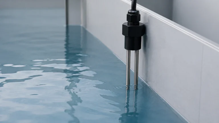
* Guided Wave Radar (GWR): Uses a physical probe to guide the microwave signal. This is particularly effective in low-dielectric liquids or applications with heavy foam, as the concentrated signal provides a stronger return echo.
Ultrasonic Level Sensors
Similar to radar, ultrasonic sensors use ToF but rely on sound waves rather than electromagnetic pulses. The sensor emits an ultrasonic pulse that bounces off the material surface. Because sound speed is influenced by air temperature, these sensors include integrated temperature compensation. They are cost-effective solutions for water treatment and simple chemical storage but have limitations in high-pressure or vacuum environments where sound cannot travel effectively.
Hydrostatic Level Transmitters
Hydrostatic measurement is based on the principle that the pressure at a specific depth is proportional to the height of the liquid column above it. By measuring the head pressure, the transmitter calculates the level based on the known density of the fluid. This method is highly reliable for vented tanks and deep wells where non-contact sensors might face line-of-sight obstructions.
Magnetic Level Gauges
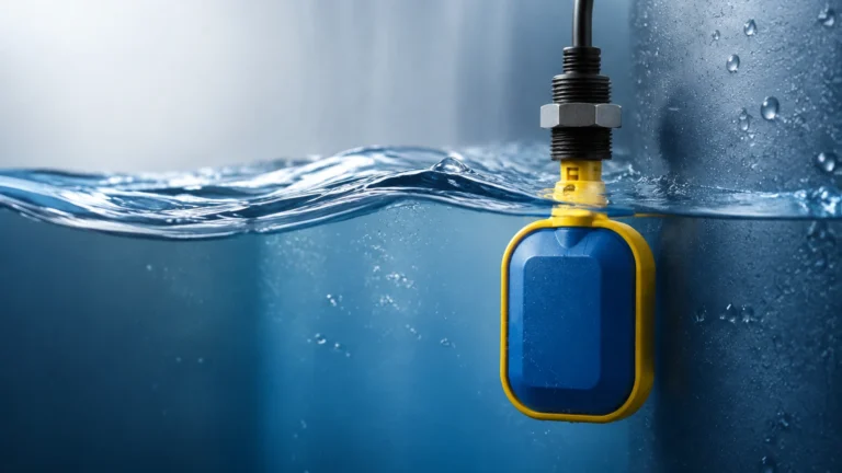
Magnetic level gauges are used for visual indication and point-level control. They utilize a float containing a permanent magnet that moves with the liquid level. As the float moves, it flips magnetic flags on an external scale and can be paired with reed switches or transmitters for remote monitoring. These are preferred in high-pressure boiler applications where electronic sensors might face extreme thermal stress.
Integration with Automation Frameworks
For users frequenting ra.rockwell.com for system configuration, the primary concern is how a Welk level meter communicates with the broader architecture. Modern level instruments are no longer isolated analog devices; they are intelligent nodes in a data network.
4-20mA and HART Protocol
The most common interface remains the 4-20mA current loop, often overlaid with the HART (Highway Addressable Remote Transducer) protocol. HART allows for bi-directional communication, enabling engineers to access diagnostic data, change calibration parameters, and monitor sensor health remotely without interrupting the analog signal. This data can be brought into the control system via HART-enabled I/O modules, which are documented extensively on major automation support sites.
Digital Communication (Modbus and Profibus)
In large-scale industrial automation, digital fieldbuses like Modbus RTU or Profibus PA are utilized to reduce wiring costs and increase data throughput. These protocols allow multiple sensors to be daisy-chained, providing a wealth of process information beyond simple level data, such as internal temperature, signal strength (echo quality), and totalized flow in open channels.
The Role of EDS and AOI
When integrating these instruments into a modern PLC environment, engineers often look for Electronic Data Sheets (EDS) or Add-On Instructions (AOI). These files simplify the mapping of the instrument’s memory into the PLC’s tag database. While the physical installation is handled at the tank, the logical installation is handled through these configuration files, ensuring that the "Main Page" of the Human Machine Interface (HMI) reflects accurate, real-time levels. For comprehensive product specifications and integration support, engineers can Review product options and application support to find the right hardware for their specific control architecture.
Practical Selection Criteria
Choosing the wrong technology leads to "ghost echoes," signal loss, and frequent maintenance cycles. The following table provides a high-level comparison to assist in the initial engineering phase.
| Technology | Typical Media | Accuracy | Pressure Range | Limitations |
| :— | :— | :— | :— | :— |
| 80GHz Radar | Liquids, Solids, Slurries | ±2mm | Up to 40 bar | High cost relative to ultrasonic |
| Ultrasonic | Water, Wastewater | ±0.25% of range | Atmospheric | Sensitive to foam and vacuum |
| Hydrostatic | Clean liquids, Oils | ±0.1% to 0.5% | Dependent on sensor | Requires constant density |
| Magnetic Gauge | Acids, High-temp water | Visual + Switch | Up to 160 bar | Moving parts; requires contact |
| Guided Wave Radar | Low-dielectric oils | ±3mm | Up to 100 bar | Probe buildup can affect signal |
Key Evaluation Questions
1. What is the dielectric constant (εr) of the medium? Radar signals require a reflection. Low-dielectric fluids (like certain oils) may require Guided Wave Radar or high-frequency 80GHz units to ensure a reliable return.
2. Is there foam or turbulence? Foam absorbs ultrasonic and radar signals. If foam is present, hydrostatic or guided wave radar is generally more reliable.
3. What is the tank geometry? Internal obstructions like agitators, heating coils, or ladders can create false reflections for non-contact sensors. In these cases, narrow-beam radar or contact-based hydrostatic sensors are preferred.
Installation Considerations and Best Practices
Proper installation is as critical as the selection of the technology itself. Even the most advanced sensor will fail if the physical mounting ignores the constraints of the technology.
Nozzle Dimensions and Positioning
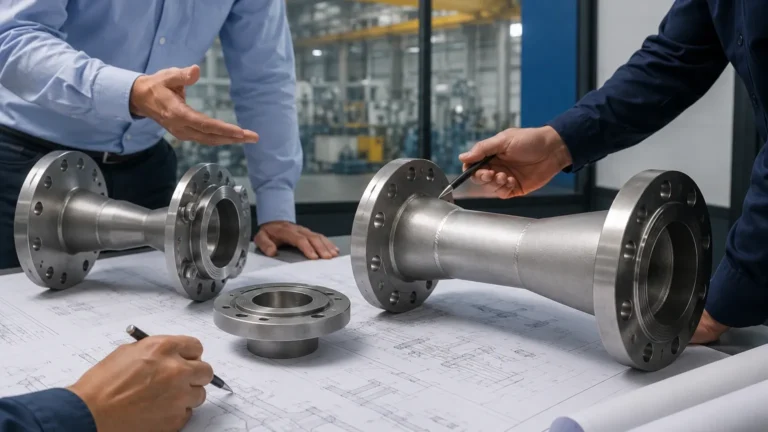
For radar and ultrasonic sensors, the nozzle height and diameter must be considered. If a nozzle is too long and narrow, the signal may reflect off the internal walls of the pipe before reaching the medium. Generally, the sensor should be positioned such that the transducer face extends slightly beyond the nozzle or follows the manufacturer's specific "dead zone" (blocking distance) requirements.
Avoiding the "Center" of the Tank
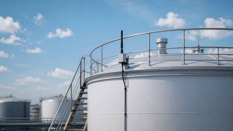
In cylindrical tanks with domed tops, sensors should never be mounted in the exact center. The parabolic shape of the tank roof can focus reflected signals back to the sensor, creating a "false high" or amplifying noise. The ideal mounting position is usually 1/3 of the radius from the tank wall.
Stilling Wells and Bypass Chambers
In applications with extreme turbulence or heavy foam, a stilling well (a vertical pipe submerged in the liquid) can be used to provide a calm surface for measurement. This is a common practice in the oil and gas industry when using radar level meters to ensure high-precision custody transfer measurements.

Limitations and Environmental Factors
While industrial level meters are designed for harsh environments, certain conditions present significant challenges:
* Vacuum Conditions: Ultrasonic sensors cannot operate in a vacuum because sound waves require a medium (air/gas) to travel. Radar is the preferred choice here.
* Heavy Dust: In solid level measurement (e.g., grain or cement silos), heavy dust can attenuate ultrasonic signals. High-frequency radar (80GHz) is better suited to penetrate dust clouds.
* Temperature Gradients: Rapid temperature changes can affect the speed of sound, leading to errors in ultrasonic readings if the integrated compensation cannot keep pace. Hydrostatic sensors are less affected by gas-phase temperature changes but must be compensated for liquid density changes.
Frequently Asked Questions (FAQ)
1. Can I use a radar level meter on a plastic tank?
Yes. Microwaves can penetrate plastic and fiberglass. It is possible to mount a radar sensor outside a plastic tank and measure the level through the roof, provided the material is not conductive and the thickness is within the sensor's penetration capability.
2. How do I handle buildup on the sensor face?
Many modern radar sensors feature "mapping" or "false echo suppression." This allows the software to recognize the static reflection from the buildup and ignore it, focusing only on the moving reflection from the liquid surface. However, for extreme buildup, a sensor with a PTFE flush-mounted antenna is recommended.
3. What is the difference between a level transmitter and a level switch?
A level transmitter provides continuous measurement (e.g., 0-100%), whereas a level switch provides a point-level alert (e.g., Tank Full/Tank Empty). Most automation systems use transmitters for process control and switches for redundant overfill protection.
4. Why is my hydrostatic sensor reading incorrectly when the tank is pressurized?
A standard hydrostatic sensor measures the pressure of the liquid plus the atmospheric pressure. If the tank is pressurized, the sensor will interpret the gas pressure as additional liquid. In these cases, a differential pressure (DP) transmitter must be used to subtract the head pressure from the total pressure.
Conclusion
Achieving precision in industrial level measurement requires a dual focus on physical application engineering and digital integration. While resources like ra.rockwell.com provide the necessary tools for the control side of the equation, the reliability of the system starts at the tank flange. By selecting the correct measurement principle—whether it be the versatility of radar, the cost-effectiveness of ultrasonic, or the ruggedness of hydrostatic transmitters—and adhering to strict installation guidelines, engineers can build systems that provide long-term accuracy and minimal maintenance. For those looking to specify hardware that bridges the gap between field reality and control logic, visiting the Main Page of a specialized manufacturer like Welk is the recommended next step in the procurement and design process.