6 Position Lever Switch
6 Position Lever Switch
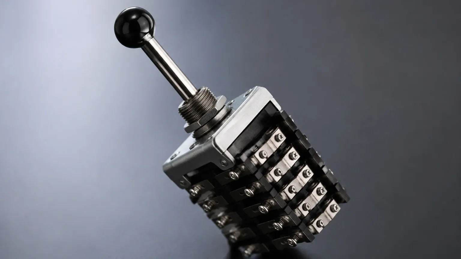
In the landscape of industrial automation and fluid management, the ability to monitor and control multiple stages of a process is critical for safety and efficiency. A 6 position lever switch, within the context of level measurement, serves as a sophisticated interface or a mechanical assembly designed to manage multi-point detection. Whether used as a selector for multiple sensors or as a multi-stage float-actuated mechanism, these devices provide the granular control necessary for complex industrial applications.
Industrial Level Switches are fundamental components in systems where simple "on/off" logic is insufficient. By integrating a 6-position configuration, engineers can monitor up to six distinct levels within a single vessel—such as high-high, high, mid-high, mid-low, low, and low-low—or toggle between six different measurement points across a facility. This article explores the technical principles, selection criteria, and installation best practices for these specialized switching solutions.
Measurement Principles of Lever-Actuated Switches
Before selecting a specific configuration, it is essential to understand the underlying physics that allow level switches to function reliably in harsh environments. Lever-actuated switches generally rely on mechanical displacement or buoyancy.
Mechanical Buoyancy and Linkage
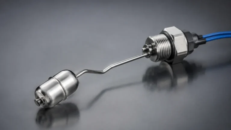
In a lever-style level switch, a float is attached to a pivot arm (the lever). As the liquid level rises or falls, the buoyancy force acting on the float moves the lever. This movement is transmitted through a sealed bellows or a magnetic coupling to an electrical switch assembly. In a multi-position setup, the lever may trigger different microswitches at specific angles of inclination, or it may be part of a rotary selector system that directs signals from six different probes to a single controller.
Multi-Point Reed Switch Technology
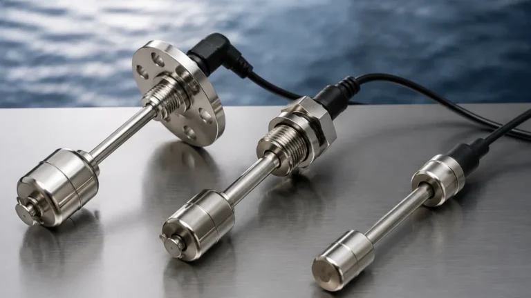
For vertical applications often associated with 6-position monitoring, a stem containing six stationary reed switches is used. A magnetic float moves along the stem; as it passes each reed switch, the circuit is opened or closed. This allows for the detection of six precise levels without the need for six separate tank penetrations. This is particularly advantageous in chemical processing and water treatment where reducing the number of vessel openings minimizes potential leak points.
Technical Specifications and Selection Criteria
Selecting the correct 6 position lever switch requires a thorough analysis of the process media and environmental conditions. The following table provides a comparison of common materials and their suitability for various industrial applications.
Selection Table: Material and Application Compatibility
| Material | Temperature Range | Pressure Rating | Common Applications |
| :— | :— | :— | :— |
| 316L Stainless Steel | -40°C to +250°C | Up to 40 bar | Oil & Gas, Food & Beverage, High-pressure steam |
| PP (Polypropylene) | -10°C to +80°C | Up to 3 bar | Water treatment, Acid/Base storage, General chemicals |
| PTFE (Teflon) | -30°C to +150°C | Up to 10 bar | Highly corrosive chemicals, Pharmaceutical processes |
| PVC | 0°C to +60°C | Up to 2 bar | Wastewater, Irrigation, Low-cost industrial monitoring |
Key Evaluation Factors
1. Fluid Density (Specific Gravity): The float must be lighter than the liquid it is intended to measure. For a 6 position lever switch to operate accurately, the specific gravity of the media should typically be above 0.5 g/cm³.
2. Viscosity: High-viscosity fluids or those prone to crystallization can impede the movement of the lever or float. In such cases, non-contact switches or heavy-duty reinforced levers are required.
3. Switching Logic: Engineers must define whether each of the six positions should be Normally Open (NO) or Normally Closed (NC). In safety-critical applications, NC is often preferred for "fail-safe" operation.
The Role of 6-Position Configurations in Process Control
While simple high/low alarms are common, the 6 position lever switch is utilized in more nuanced control loops. These configurations are often found in:
* Sequential Pump Control: Managing a lead-lag pump system where multiple pumps are activated or deactivated based on the rising or falling levels across six setpoints.
* Inventory Management: Providing a rough percentage-based volume reading (e.g., 0%, 20%, 40%, 60%, 80%, 100%) for tanks where continuous radar measurement might be cost-prohibitive.
* Multi-Zone Alarms: Segregating operational zones from emergency zones to prevent overfills or dry-run conditions in large-scale industrial boilers.
Installation and Wiring Best Practices
Proper installation is paramount to ensuring the longevity and accuracy of Level Switches. For 6-position models, the complexity of the wiring and the mechanical alignment requires precise execution.
Mounting Considerations
* Orientation: Lever switches are typically side-mounted. Ensure that the lever arm has a full range of motion without hitting internal baffles, ladders, or agitators. For multi-point vertical switches, ensure the stem is perfectly plumb to prevent float sticking.
* Nozzle Length: The mounting nozzle should not be so long that it interferes with the lever's pivot point. A standard 50mm to 100mm (2" to 4") nozzle is usually sufficient, but this must be verified against the switch's specific geometry.
* Sealing: Use appropriate gaskets (EPDM, Viton, or PTFE) and thread sealants compatible with the process media to prevent leaks at the mounting point.
Electrical Integration
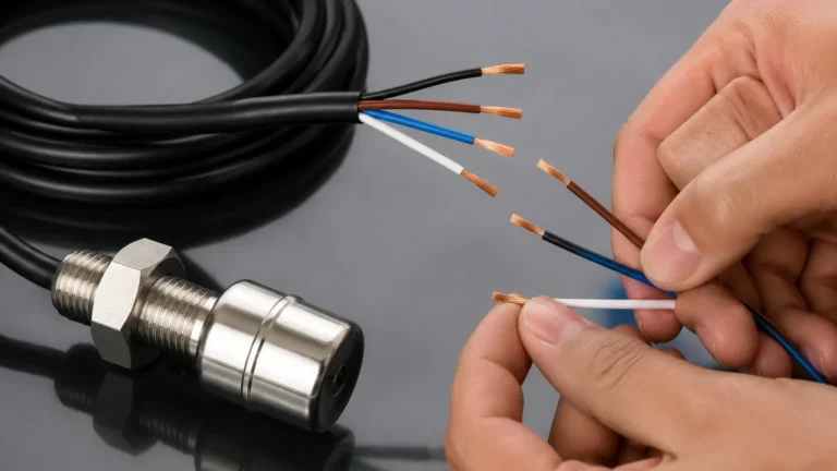
* Cable Management: A 6-position switch involves multiple conductors. Use shielded cables to prevent electromagnetic interference (EMI) from nearby motors or VFDs.
* Contact Protection: If switching inductive loads (like solenoid valves or motor starters), use RC snubbers or diodes to protect the switch contacts from voltage spikes.
* Terminal Marking: Clearly label each of the six output pairs. In a B2B industrial environment, standardized labeling according to P&ID (Process and Instrumentation Diagram) nomenclature is essential for future maintenance.
Limitations and Common Risks
Despite their reliability, 6 position lever switches have specific limitations that must be addressed during the design phase:
* Mechanical Wear: Because these are moving parts, the pivot points and seals (bellows) are subject to fatigue over time. Regular inspection intervals are necessary.
* Turbulence: In tanks with high agitation, the lever may bounce, leading to "chattering" of the electrical contacts. This can be mitigated by using a stilling well or an electronic time-delay relay in the control panel.
* Buildup and Scaling: In wastewater or mining slurries, material can build up on the lever or float, increasing its weight and causing it to fail in the "down" position. Coated floats or periodic cleaning are the standard solutions.
Maintenance and Troubleshooting Checklist
To maintain operational uptime, the following maintenance routine is recommended for multi-point switching systems:
1. Visual Inspection: Check for signs of corrosion on the housing and leaks at the process connection.
2. Manual Actuation: If the tank can be bypassed, manually move the lever or float to ensure all six positions trigger the corresponding alarms in the PLC/SCADA system.
3. Resistance Testing: Measure the contact resistance of the switches. High resistance (above 1-2 ohms) may indicate pitted or oxidized contacts.
4. Cleaning: Remove any biological growth or chemical scale from the wetted parts using a compatible solvent or soft brush.
Frequently Asked Questions (FAQ)
Q: Can a 6 position lever switch be used in hazardous areas?
A: Yes, provided the switch is housed in an explosion-proof enclosure (Ex d) or is wired through an intrinsically safe (IS) barrier (Ex i). Always check the ATEX, IECEx, or UL certifications on the product data sheet.
Q: What is the difference between a 6-position selector switch and a 6-point level switch?
A: A 6-position selector switch is usually a manual control panel component used to choose between different sensor inputs. A 6-point level switch is an instrument installed on a tank that automatically detects six different liquid levels.
Q: How do I handle signal bounce in turbulent liquids?
A: The most effective method is to implement a software debounce in the PLC (typically 2-5 seconds) or to install the switch inside a stilling well (a pipe that dampens surface waves).
Q: Is it possible to adjust the setpoints of a 6-position switch after installation?
A: For mechanical lever switches, setpoints are usually fixed by the geometry of the device. For vertical reed-switch stems, some models allow the user to slide the reed switches along the internal track, but this often requires removing the unit from the tank.
By understanding the mechanical requirements and environmental constraints of the 6 position lever switch, engineering teams can implement robust level control strategies that enhance plant safety and process consistency. For more detailed product specifications and custom configurations, refer to the technical documentation provided by professional manufacturers.