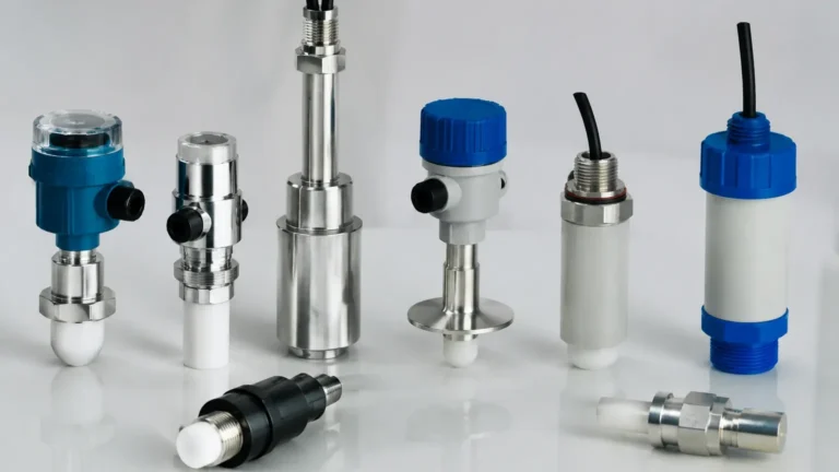
6 Lead Switch
6 Lead Switch
In the landscape of industrial automation and process control, the ability to accurately detect the presence or absence of a substance at a specific point is fundamental. Level switches serve this purpose, acting as the binary eyes of a system. Among the various electrical configurations available, the 6 lead switch configuration—typically associated with Double Pole Double Throw (DPDT) relay outputs—stands out as a robust solution for engineers requiring redundancy, multi-circuit control, or enhanced safety protocols.
Welk, a specialist in industrial level measurement, provides a variety of Level Switches designed to integrate seamlessly into complex control loops. Understanding the wiring, principles, and selection criteria for these devices is essential for ensuring long-term operational reliability in sectors ranging from wastewater treatment to chemical processing.
Principles of Level Measurement and Switching
Before diving into the specifics of a 6 lead switch configuration, it is necessary to understand the physical principles that trigger these devices. A level switch does not provide continuous data; rather, it changes state when the material reaches a predetermined height.
Mechanical and Electromechanical Principles
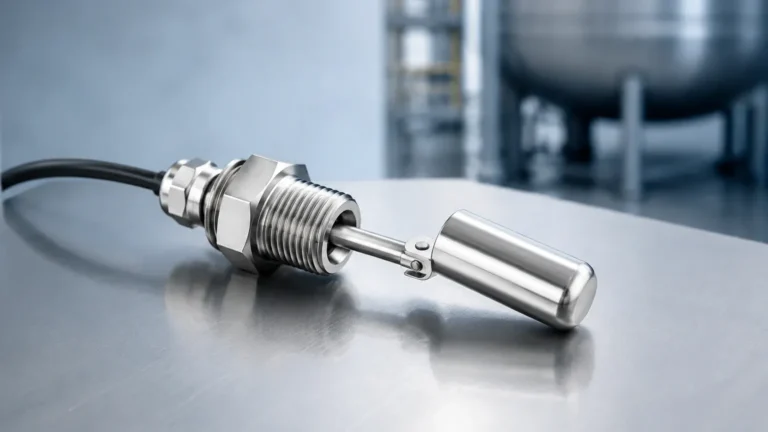
1. Float Switches: These utilize buoyancy. A float containing a magnet moves with the liquid level. When it reaches a reed switch or actuates a microswitch via a lever, the circuit is toggled. In high-demand applications, these are often configured with 6 leads to provide dual output signals.
2. Rotary Paddle Switches: Primarily used for bulk solids and powders. A motor slowly rotates a paddle. When the material covers the paddle, the resulting torque trips a switch. A 6 lead version allows the motor power and the dual-contact signal outputs to be managed effectively.
Electronic and Vibrational Principles
1. Vibrating Level Switches (Tuning Forks): These sensors vibrate at a specific resonant frequency (typically around 1,200 Hz for liquids). When the medium covers the fork, the frequency drops, which the electronics detect to trigger the relay.
2. Capacitance Switches: These measure the change in capacitance between the probe and the tank wall. They are ideal for sticky or corrosive substances where moving parts would fail.
3. Ultrasonic and Radar Switches: While often used for continuous measurement, they can be configured as point switches. These use Time-of-Flight (ToF) principles to determine if a surface has reached a specific threshold.
Understanding the 6 Lead Switch Configuration
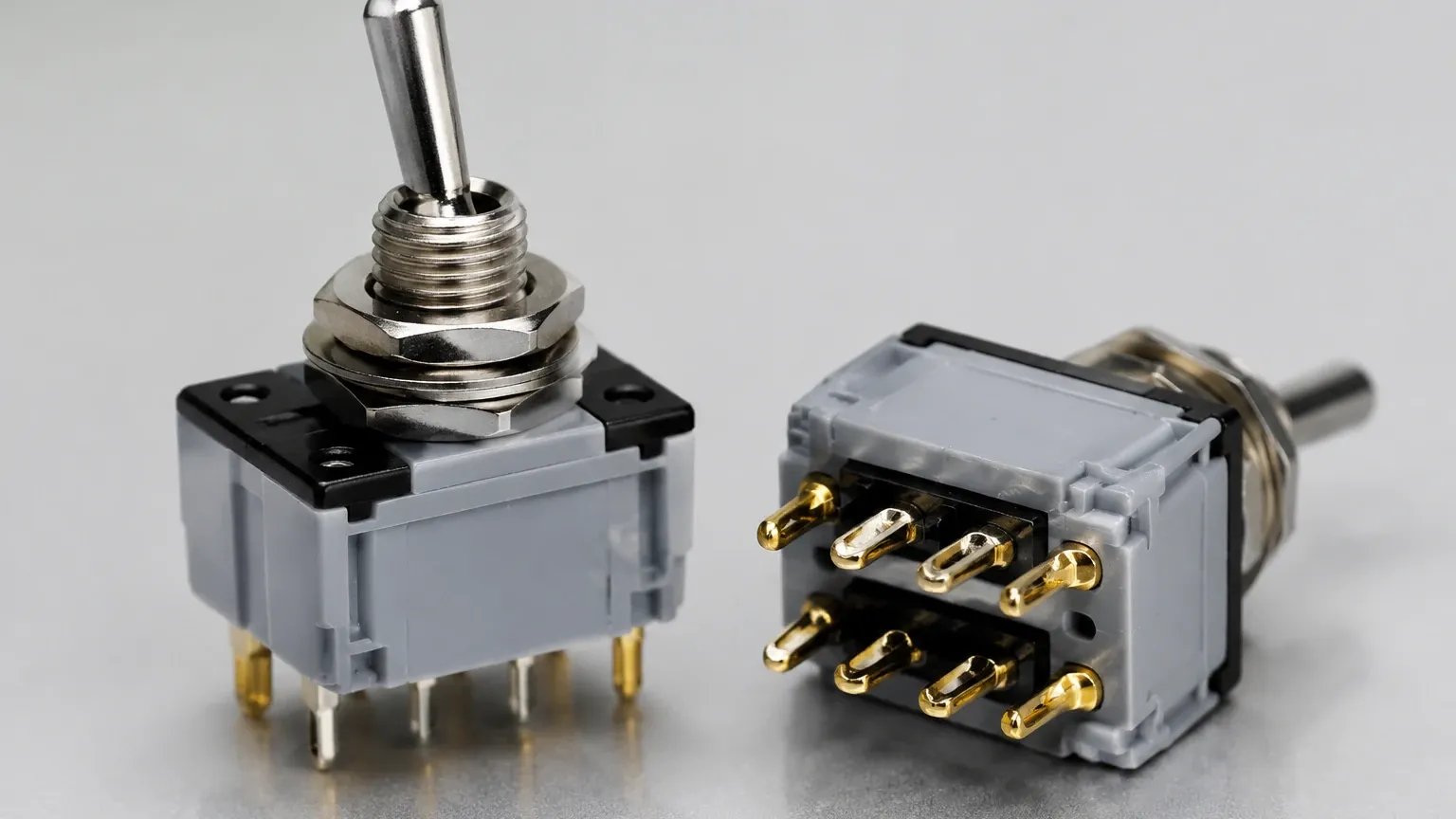
The term "6 lead switch" refers to the number of electrical conductors exiting the switch housing or available at the terminal block. In the context of industrial relays, this almost always signifies a DPDT (Double Pole Double Throw) contact arrangement.
The DPDT Architecture
A standard Single Pole Double Throw (SPDT) switch has 3 leads: Common (COM), Normally Open (NO), and Normally Closed (NC). A 6 lead switch essentially houses two of these circuits within a single device, operated by the same physical mechanism. The wiring breakdown is as follows:
* Lead 1: Pole 1 Common (COM1)
* Lead 2: Pole 1 Normally Open (NO1)
* Lead 3: Pole 1 Normally Closed (NC1)
* Lead 4: Pole 2 Common (COM2)
* Lead 5: Pole 2 Normally Open (NO2)
* Lead 6: Pole 2 Normally Closed (NC2)
Why Use 6 Leads?
1. Redundancy: If one set of contacts fails due to electrical arcing or mechanical wear, the second set acts as a backup.
2. Dual Load Control: One set of leads can trigger a local alarm (e.g., a strobe light or siren), while the second set sends a signal to a Programmable Logic Controller (PLC) or Distributed Control System (DCS).
3. Voltage Isolation: The two poles are electrically isolated. This allows an engineer to use one pole for a 24V DC signal to a PLC and the other pole to switch a 230V AC pump motor directly, provided the switch is rated for such loads.
Selection Criteria for 6 Lead Level Switches
Choosing the correct switch requires a balance between the physical properties of the medium and the electrical requirements of the control system. The following table provides a comparison of common technologies that utilize 6 lead configurations.
Practical Selection Table
| Technology | Media Compatibility | Max Temperature | Max Pressure | Best Use Case |
| :— | :— | :— | :— | :— |
| Magnetic Float | Clean liquids, oils | Up to 200°C | 40 bar (4.0 MPa) | High-pressure tanks, fuel storage. |
| Tuning Fork | Liquids, light powders | -40°C to 150°C | 25 bar (2.5 MPa) | Overfill protection, pump dry-run prevention. |
| Rotary Paddle | Grains, sand, cement | -20°C to 80°C | Atmospheric | Silos and hoppers for dry bulk solids. |
| Capacitance | Slurries, acids, interfaces | Up to 250°C | 100 bar (10.0 MPa) | Corrosive chemicals or high-viscosity media. |
Material Compatibility
The wetted parts of the switch must be compatible with the process media. Stainless steel (316L) is the industry standard for most water and chemical applications. For highly aggressive acids, PTFE or PVDF coatings are required. When selecting a 6 lead switch, ensure the housing (often aluminum or plastic) provides adequate protection against the external environment (e.g., IP66 or IP67 ratings).
Installation and Wiring Considerations
Proper installation is the difference between a reliable safety device and a frequent maintenance headache. Because a 6 lead switch involves more complex wiring, the following steps are critical:
1. Conduit and Cable Entry
Industrial switches usually feature one or two conduit entries (e.g., M20 x 1.5 or 1/2" NPT). When wiring 6 leads, ensure the cable gland is sized correctly for a multi-core cable. Using a single 6-core cable is often more efficient than running multiple smaller cables, as it maintains the environmental seal of the housing.
2. Wiring for Safety (Fail-Safe Modes)
In level switching, "Fail-Safe" refers to the state the switch assumes if power is lost.
* High-Level Alarm (Fail-Safe High): The relay should be energized when the level is low and de-energize when the level is high or power is lost. This ensures that a broken wire is treated as a high-level alarm.
* Low-Level Alarm (Fail-Safe Low): The relay is energized when the level is high and de-energizes when the level drops or power fails.
3. Grounding and Shielding
For electronic switches (tuning forks or capacitance), the 6 leads may include a dedicated ground or shield. Proper earthing prevents electromagnetic interference (EMI) from inducing false trips in the sensitive electronics of the switch.
Limitations and Operational Risks
While the 6 lead DPDT configuration offers versatility, it is not without limitations:
* Contact Rating: Just because a switch has 6 leads does not mean it can handle high-current motors. Always check the contact rating (e.g., 5A @ 250V AC). For heavy motors, use the 6 lead switch to trigger an external contactor.
* Mechanical Wear: In float or paddle switches, the mechanical components will eventually fatigue. Regular testing of both poles is necessary to ensure the redundancy is still functional.
* Build-up and Coating: For tuning forks and capacitance probes, excessive material build-up can cause the switch to remain in the "covered" state even after the level has dropped. Selecting a switch with "active shield" technology or a self-cleaning vibration profile can mitigate this.
Maintenance and Troubleshooting
A proactive maintenance schedule for a 6 lead switch should include:
1. Visual Inspection: Check for moisture ingress in the housing and corrosion on the terminals.
2. Continuity Testing: Use a multimeter to verify that both sets of contacts (Pole 1 and Pole 2) toggle simultaneously when the switch is actuated manually or by the process level.
3. Cleaning: For wetted parts, remove any scale or biological growth that might impede the movement of a float or the vibration of a fork.
Frequently Asked Questions (FAQs)
Q: Can I use a 6 lead switch as a 3 lead switch?
A: Yes. You can simply use one set of contacts (COM, NO, NC) and leave the other three leads disconnected. However, it is a best practice to cap the unused leads to prevent accidental short circuits.
Q: What is the difference between a 5 lead and a 6 lead switch?
A: A 5 lead switch usually indicates a DPDT relay where the two Common (COM) terminals are internally bridged, or it might be a configuration with 24V DC power leads (2) and an SPDT output (3). A true 6 lead switch provides two entirely independent circuits.
Q: Are 6 lead switches suitable for hazardous areas?
A: Yes, provided the switch is certified (e.g., ATEX, IECEx, or UL Class/Div). In these cases, the 6 leads must be wired through appropriate intrinsic safety barriers or housed in explosion-proof enclosures.
Q: How do I know which lead is which?
A: Manufacturers like Welk provide a wiring diagram inside the housing cover or in the technical manual. Standard color-coding exists, but it varies by region (e.g., DIN vs. US standards), so always refer to the specific product datasheet.
Conclusion
The 6 lead switch is a cornerstone of industrial process safety, offering the flexibility to manage multiple signals from a single point of detection. Whether you are preventing a tank overflow with a tuning fork or managing bulk solids with a rotary paddle, the DPDT configuration provided by 6 leads ensures that your control system has the redundancy it needs. By following strict selection criteria and adhering to proper installation practices, engineers can significantly reduce downtime and enhance the safety of their operations.
For more technical specifications on various switching technologies, you can explore the full range of Level Switches to find the ideal match for your specific industrial application.