Floatless Level Switch 61f G2
Floatless Level Switch 61f G2
In industrial automation and water management, the reliability of liquid level control systems is paramount. Among the various technologies available, the conductive level switch—often referred to as a floatless level switch—stands out for its simplicity, durability, and lack of moving parts. The floatless level switch 61f g2 is a specific industrial standard used extensively for automatic water supply and drainage control.
As a professional manufacturer of industrial level measurement instruments, Welk provides a range of Level Switches designed to meet the rigorous demands of chemical processing, water treatment, and industrial automation. Understanding the operational principles and installation requirements of the 61F-G2 model is essential for engineers tasked with designing robust fluid control systems.
Understanding Conductive Level Measurement Principles
Before selecting a specific model like the 61F-G2, it is necessary to understand the underlying physics of conductive level measurement. Unlike float switches that rely on buoyancy and mechanical movement, floatless switches utilize the electrical conductivity of the liquid being measured.
The Electrode Circuit
The system typically consists of a controller (the 61F-G2 unit) and an electrode holder containing three or more stainless steel rods (electrodes) of varying lengths. These electrodes are designated as:
1. E1 (High Level): The shortest electrode, which determines the point where the pump stops (for supply) or starts (for drainage).
2. E2 (Low Level): The intermediate electrode, which determines the point where the pump starts (for supply) or stops (for drainage).
3. E3 (Common): The longest electrode, which must always remain submerged to provide a ground reference for the circuit.
When the conductive liquid touches both the common electrode (E3) and a level electrode (E1 or E2), a low-voltage AC circuit is completed. The controller detects this minute current flow and toggles an internal relay to operate pumps, valves, or alarms. Using AC voltage instead of DC is critical to prevent electrolysis and electrode corrosion over time.
Overview of the Floatless Level Switch 61f G2
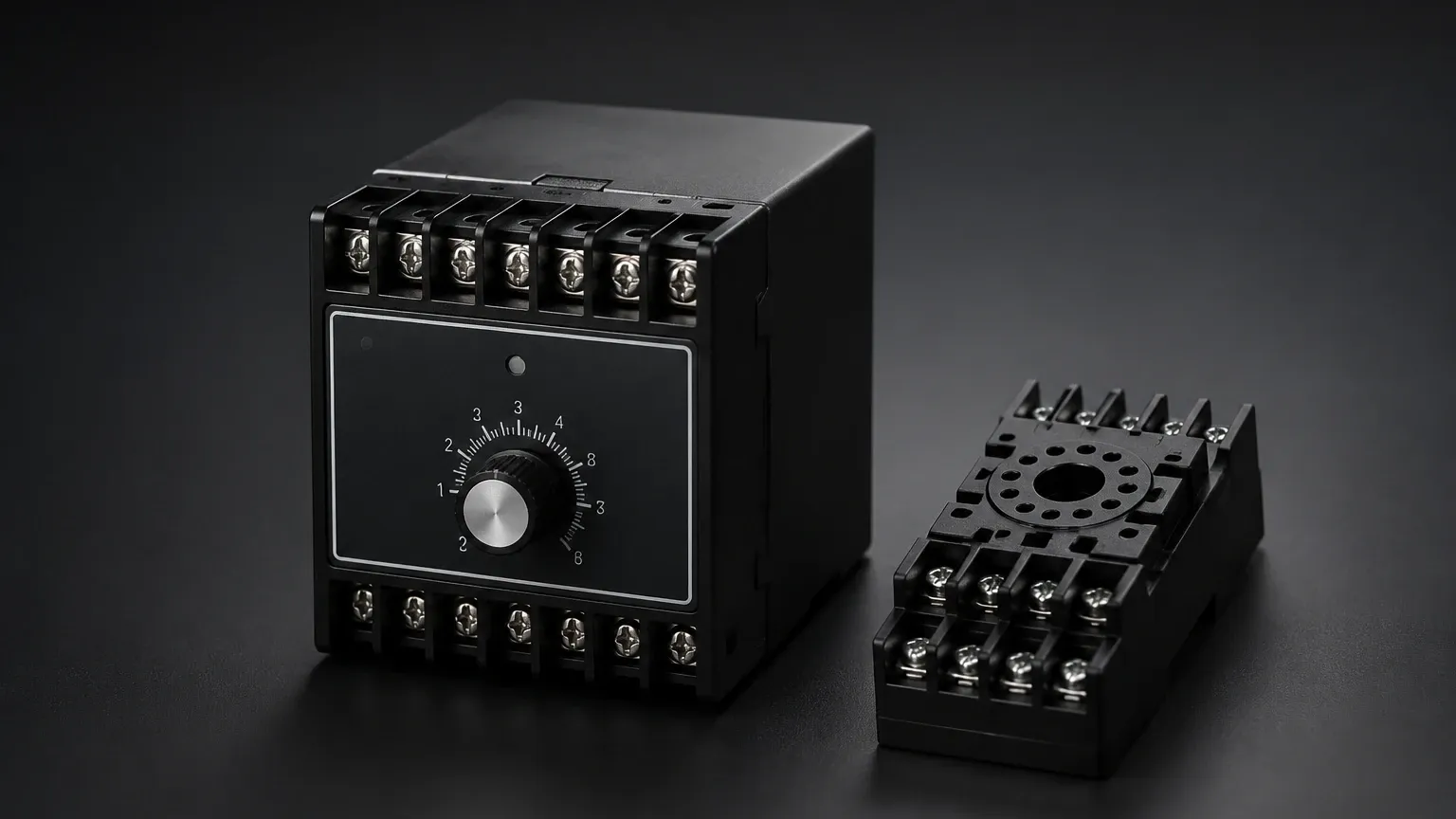
The 61F-G2 is a compact, plug-in style controller designed specifically for automatic water supply and drainage. It is characterized by its integrated design, which simplifies wiring compared to modular multi-component systems.
Primary Functions
In a standard configuration, the 61F-G2 performs two main roles:
* Automatic Water Supply: The relay activates the pump when the water level drops below E2 and stops it when the level reaches E1.
* Automatic Drainage: The relay activates the pump when the water level reaches E1 and stops it when it falls below E2.
This "differential" or "hysteresis" control prevents the pump from "hunting" (rapidly cycling on and off) due to surface ripples or minor fluctuations in the liquid level.
Technical Specifications and Selection Criteria
Selecting the correct floatless level switch requires matching the electrical properties of the liquid with the sensitivity of the controller. The 61F-G2 is generally suited for general-purpose applications involving tap water or wastewater.
Selection Table: 61F-G2 Series Overview
| Feature | Specification (Standard 61F-G2) | High-Sensitivity Variant |
| :— | :— | :— |
| Supply Voltage | 110/220 VAC (50/60 Hz) | 110/220 VAC |
| Inter-electrode Voltage | 8 VAC | 24 VAC |
| Power Consumption | Approx. 3.5 VA | Approx. 4.0 VA |
| Response Time | Operate: 80 ms max; Release: 160 ms max | 150 ms max |
| Control Output | 5 A at 250 VAC (Resistive load) | 3 A at 250 VAC |
| Ambient Temperature | -10°C to 55°C (14°F to 131°F) | -10°C to 55°C |
| Max. Cable Length | 1 km (3,280 ft) | 50 m (164 ft) |
Key Evaluation Criteria
When evaluating the floatless level switch 61f g2 for a project, engineers should confirm the following:
* Liquid Conductivity: The liquid must have an inter-electrode resistance low enough to trigger the relay. Pure deionized water or oil cannot be measured with this technology.
* Distance to Electrodes: If the controller is located in a control room far from the tank, cable capacitance can cause false triggering. For distances exceeding 100 meters (328 ft), specific long-distance models or shielded cables are required.
* Mounting Space: The 61F-G2 typically uses an 8-pin or 11-pin circular socket. Ensure sufficient DIN rail space or panel depth is available.
Installation Guidelines and Wiring Configurations
Proper installation is the most critical factor in ensuring the longevity of a conductive level system. Errors in electrode placement or wiring are the leading causes of system failure.
Electrode Installation
1. Spacing: Electrodes should be kept at least 10 mm to 20 mm (0.4 to 0.8 inches) apart to prevent accidental contact or debris bridging. In turbulent tanks, use electrode separators.
2. Length Adjustment: Stainless steel rods are typically supplied in 1-meter lengths and can be connected using coupling nuts. Ensure the E3 (common) electrode is at least 50 mm (2 inches) longer than the lowest control electrode (E2).
3. Staggering: If the liquid is prone to foaming or heavy ripples, consider installing the electrodes inside a stilling well (a perforated pipe) to stabilize the surface measurement.
Wiring the 61F-G2
The wiring depends on whether the application is for supply or drainage.
* For Water Supply: Connect the pump contactor to the Normally Closed (NC) contacts of the relay. When the level is low (circuit broken), the relay is de-energized, and the NC contact remains closed, powering the pump.
* For Drainage: Connect the pump contactor to the Normally Open (NO) contacts. When the level reaches E1 (circuit completed), the relay energizes, closing the NO contact and starting the drainage pump.
Limitations and Application Constraints
While the floatless level switch 61f g2 is a highly reliable tool, it is not a universal solution. Engineers must recognize the following limitations:
* Non-Conductive Liquids: This technology is entirely unsuitable for oils, diesel, pure distilled water, or solid powders. For these media, Welk recommends Level Switches based on ultrasonic or tuning fork principles.
* Coating and Scaling: In wastewater applications, grease or calcium carbonate (scale) can build up on the electrodes. This creates an insulating layer that prevents the current from flowing, leading to a failure to detect the liquid level.
* Corrosive Environments: While the rods are typically 304 or 316 stainless steel, highly aggressive chemicals may require titanium or Hastelloy electrodes with specialized insulation.
* High Pressure/Temperature: The standard electrode holders are often rated for atmospheric pressure. For pressurized boilers or high-temperature reactors, specialized ceramic-to-metal sealed electrode holders are mandatory.
Comparison: Floatless vs. Float-Type Switches
| Feature | Floatless (Conductive) | Float-Type (Mechanical) |
| :— | :— | :— |
| Moving Parts | None | Pivot arms, floats, or magnets |
| Maintenance | Low (Cleaning electrodes) | Medium (Checking for mechanical binding) |
| Reliability | High in clean liquids | Subject to mechanical fatigue |
| Liquid Types | Conductive only | Almost any liquid |
| Installation | Top-down only | Top, side, or bottom mount |
Maintenance and Troubleshooting
To maintain the accuracy of a floatless level switch 61f g2 system, a semi-annual inspection is recommended.
Common Issues and Solutions
* Pump Won't Start: Check the voltage across the power supply pins. If power is present, bridge the E1 and E3 terminals with a wire; if the relay clicks, the issue is likely scale buildup on the electrodes or the liquid conductivity is too low.
* Pump Won't Stop: This is often caused by "tracking" or moisture in the electrode holder head, creating a conductive path even when the liquid has receded. Clean and dry the holder assembly.
* Rapid Cycling: Ensure that the E1 and E2 electrodes are not cut to the same length. There must be a physical gap between the start and stop levels to provide hysteresis.
Frequently Asked Questions (FAQ)
Q: Can I use the 61F-G2 with seawater?
A: Yes, seawater is highly conductive. However, you must use high-grade stainless steel (316L) or titanium electrodes to prevent rapid galvanic corrosion.
Q: What is the maximum length of the electrode rods?
A: Mechanically, rods can be extended many meters using couplings, but they become prone to swaying. For deep wells exceeding 5 meters (16 ft), weighted cable electrodes (suspended by insulated wires) are preferred over rigid rods.
Q: Can one 61F-G2 control two different tanks?
A: No. A single 61F-G2 is designed for one set of logic (supply or drainage). To control two tanks independently, two controllers are required.
Q: Is the 61F-G2 safe for potable water?
A: The controller itself is external to the tank. As long as the electrodes and holders used are food-grade or certified for drinking water, the system is perfectly safe as the current passing through the water is negligible (micro-amps).
For complex industrial environments involving hazardous chemicals or non-conductive media, exploring alternative Level Switches such as radar or ultrasonic sensors may be necessary. Welk provides comprehensive technical support to help determine the most cost-effective and accurate measurement technology for your specific application.