Linc Level Switches
Linc Level Switches
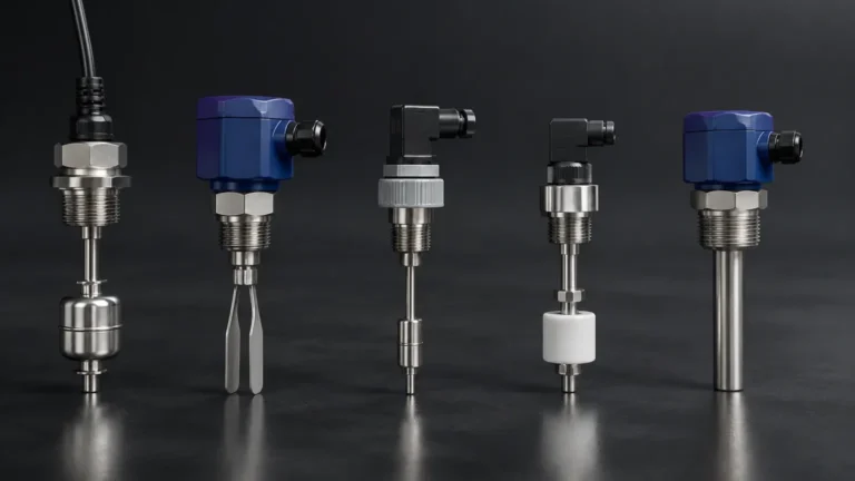
In the landscape of industrial process control, the ability to detect discrete liquid levels is fundamental for safety, overflow prevention, and pump control. Among the various technologies available, linc level switches have established a reputation for reliability, particularly in the demanding environments of the oil and gas, chemical processing, and water treatment industries. These devices are primarily float-operated and are designed to provide either pneumatic or electric signals when a specific liquid level is reached.
For engineers and facility managers, selecting the right point-level detection technology requires a deep understanding of the mechanical principles involved, the specific environmental constraints of the application, and the long-term maintenance requirements. This guide provides a technical overview of the principles, selection criteria, and installation best practices for these robust instruments.
Understanding the Principles of Float-Operated Level Switches
Before evaluating specific models of linc level switches, it is essential to understand the underlying physics of float-operated measurement. These devices rely on the principle of buoyancy, as defined by Archimedes' Principle, which states that any object, wholly or partially immersed in a fluid, is buoyed up by a force equal to the weight of the fluid displaced by the object.
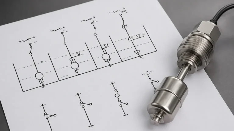
In a typical level switch configuration, a float is attached to a lever arm or a vertical stem. As the liquid level rises within a vessel or an external chamber, the float moves upward. This mechanical movement is then translated into a switching action. There are two primary methods for this translation:
1. Magnetic Coupling: The float contains a permanent magnet. As the float moves, the magnetic field actuates a reed switch or a microswitch located outside the process pressure boundary. This design ensures that the electrical components are completely isolated from the process media, minimizing the risk of leaks.
2. Mechanical Snap-Action: In many pneumatic versions, the movement of the float directly operates a pilot valve or a snap-acting mechanism. This is particularly common in remote locations where electrical power is unavailable, allowing the switch to control pneumatic pumps or valves directly using the process gas or compressed air.
These Level Switches are categorized as "point level" sensors because they do not provide a continuous measurement of the level (e.g., 0–100%); instead, they indicate whether the liquid is above or below a specific physical point.
Technical Specifications and Design Varieties
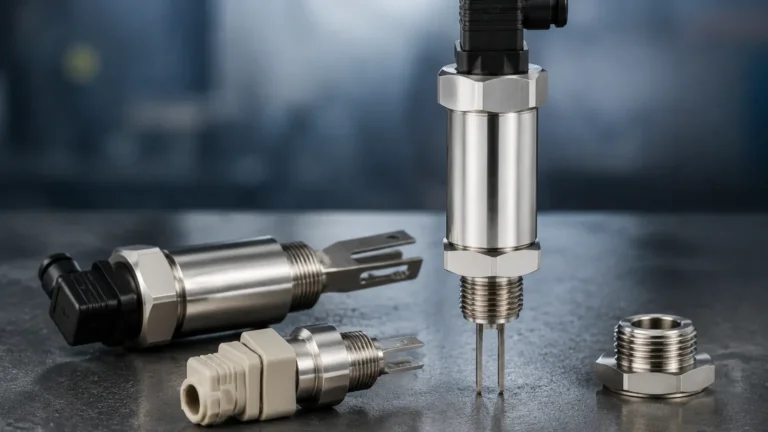
Linc level switches are engineered to handle high-pressure and high-temperature environments that would often cause electronic sensors to fail. They are commonly constructed from 316 stainless steel, though exotic materials like Monel or Hastelloy are used for highly corrosive media.
Pneumatic vs. Electric Actuation
The choice between pneumatic and electric models is usually dictated by the available infrastructure and the safety requirements of the site:
* Pneumatic Switches: These are the workhorses of the oilfield. They use a 1.4 to 4.1 bar (20 to 60 psi) air or gas supply. When the level reaches the set point, the switch opens or closes a pilot valve, venting or applying pressure to a control circuit. They are inherently explosion-proof because they do not use electricity.
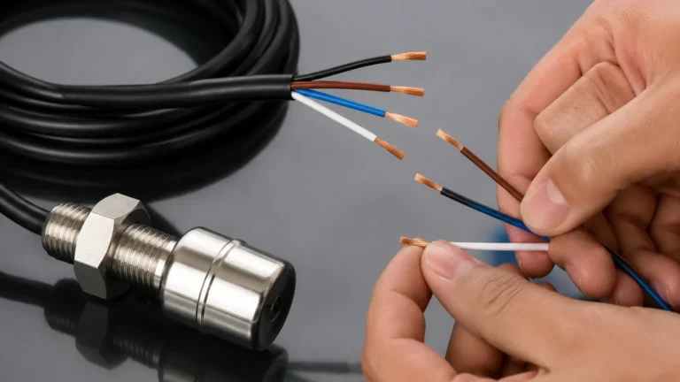
* Electric Switches: These utilize SPDT (Single Pole Double Throw) or DPDT (Double Pole Double Throw) microswitches. They are ideal for integration into modern PLC (Programmable Logic Controller) or SCADA systems. For hazardous areas, these must be housed in explosion-proof enclosures or used with intrinsically safe barriers.
Key Selection Criteria for Industrial Applications
Selecting the appropriate level switch involves more than just matching the pipe size. Engineers must consider the specific gravity of the liquid, the operating pressure, and the chemical compatibility. Below is a practical selection table for evaluating linc level switches and similar float-operated devices.
Selection Evaluation Table
| Parameter | Requirement | Considerations |
| :— | :— | :— |
| Specific Gravity (SG) | Minimum 0.4 to 0.6 | The float must be lighter than the liquid it displaces. Lower SG requires larger floats. |
| Operating Pressure | Up to 103 bar (1500 psi) | High-pressure applications require thicker float walls, which increases weight and affects buoyancy. |
| Temperature Range | -40°C to 204°C (-40°F to 400°F) | Standard seals (Viton/Buna-N) must be checked against process temperature and chemistry. |
| Mounting Type | NPT, Flanged, or External Chamber | Internal mounting is cost-effective; external chambers allow for maintenance without tank shutdown. |
| Output Type | Pneumatic (Snap/Throttling) or Electric | Determine if the final control element is an air-actuated valve or an electronic alarm. |
Installation and Calibration Best Practices
Correct installation is critical for the longevity of linc level switches. Because these are mechanical devices, they are susceptible to physical interference and vibration.
Orientation and Positioning
In horizontal mounting configurations, the switch must be perfectly level to ensure the float arm moves freely through its entire arc. If the switch is tilted, the internal friction may increase, leading to a "stuck" switch condition. For vertical installations, ensure the stem is not bent during the insertion process.
Turbulence and Stillwells
In tanks with heavy agitation or splashing, the float may bounce, causing "chatter" in the electrical or pneumatic signal. This can lead to premature wear of the switch contacts or the valve seats. In such cases, installing the switch inside a stillwell (a vertical pipe that dampens surface turbulence) is highly recommended.
External Cage Mounting
For many process plants, mounting the switch in an external cage (or bridle) is the preferred method. This allows the switch to be isolated from the main vessel using block valves, enabling testing, calibration, and maintenance without depressurizing the entire system.

Common Risks and Operational Limitations
While linc level switches are exceptionally durable, they are not universal solutions. Understanding their limitations prevents unexpected downtime.
1. Media Coating and Buildup: If the process liquid is highly viscous or prone to crystallization (such as crude oil with high paraffin content), the material can build up on the float or the pivot arm. This increases the weight of the float and can eventually pin it in one position.
2. Mechanical Wear: Because these switches have moving parts, the pivot pins and seals will eventually wear out. In high-cycle applications (e.g., a sump pump that cycles every few minutes), regular inspection intervals must be established.
3. Interface Measurement Challenges: Using a float switch to detect the interface between two liquids (like oil and water) requires a float weighted specifically for the density of the lower liquid but not the upper one. If the densities of the two liquids change due to temperature fluctuations, the switch point will drift.
4. Pressure Surges: Sudden pressure spikes in a pneumatic system can damage the internal pilot valves of a pneumatic switch. Using a pressure regulator on the supply line is a standard protective measure.
Maintenance and Troubleshooting Guide
A proactive maintenance schedule for linc level switches should include a physical "bucket test" or a manual lift of the float arm at least once a year to verify the switching action.
* If the switch fails to actuate: Check for debris lodged in the float mechanism or a collapsed float. In high-pressure applications, a pinhole leak can cause the float to fill with liquid and sink.
* If a pneumatic switch is constantly venting: This usually indicates a worn O-ring or a damaged seat within the pilot valve assembly. Most linc level switches are designed to be field-repairable with standard seal kits.
* If an electric switch provides intermittent signals: Inspect the wiring for corrosion, especially in humid or coastal environments. Ensure the conduit entry is sealed with a packing gland to prevent moisture ingress into the switch housing.
Frequently Asked Questions (FAQs)
Q: Can linc level switches be used in sanitary applications?
A: While standard models are designed for industrial use, versions with polished stainless steel finishes and Tri-Clamp connections are available. However, for food and beverage applications, non-contact sensors like ultrasonic or radar are often preferred to avoid microbial growth on moving parts.
Q: What is the difference between a snap-acting and a throttling pneumatic switch?
A: A snap-acting switch provides an immediate, full-pressure output once the set point is reached, which is ideal for on/off pump control. A throttling switch provides a variable output pressure proportional to the float position, often used for basic level control in separators.
Q: How do I handle high-vibration environments?
A: For applications on reciprocating compressors or vibrating skids, use heavy-duty mounting brackets and consider remote-mounted electronics. Magnetic coupling is generally more resistant to vibration than direct mechanical linkages.
Q: Are these switches compatible with H2S (Sour Gas)?
A: Yes, but you must specify NACE MR0175/ISO 15156 compliance. This ensures the metallic components are resistant to sulfide stress cracking.
By carefully matching the switch specifications to the process conditions and following rigorous installation standards, linc level switches provide a cost-effective and dependable solution for critical point-level monitoring. For applications requiring continuous level data or non-contact measurement, exploring a broader range of industrial instrumentation may be necessary to ensure optimal process efficiency.