Floatless Level Switch 61f Gp N
Floatless Level Switch 61f Gp N
In the landscape of industrial automation and fluid management, the floatless level switch 61f gp n represents a cornerstone technology for conductive liquid control. Unlike traditional mechanical float switches that rely on buoyancy and moving parts, floatless controllers utilize the electrical conductivity of the liquid itself to complete a circuit. This method offers significant advantages in terms of reliability, maintenance, and space efficiency. For engineers and facility managers, understanding the nuances of the 61F-GP-N series is essential for implementing robust level control systems in applications ranging from simple water tank management to complex industrial wastewater treatment.
Measurement Principle of Conductive Level Control
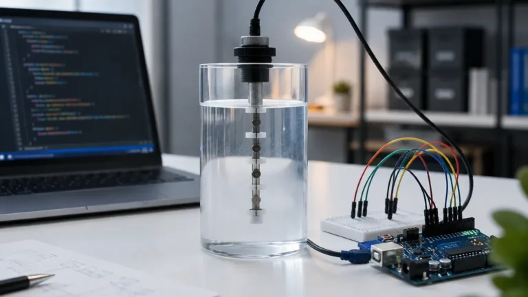
The floatless level switch 61f gp n operates on the principle of conductivity. The system typically consists of a controller (the 61F-GP-N unit) and a set of electrodes submerged in the liquid.
The Electrode Circuit
When the liquid level rises and touches the electrodes, a low-voltage alternating current (AC) flows through the liquid between the electrodes. This current is sensed by the controller's internal circuitry, which then activates a relay. The use of AC voltage is critical; it prevents electrolysis, which would otherwise lead to the rapid corrosion of the electrodes and the decomposition of the liquid if direct current (DC) were used.
Three-Electrode System
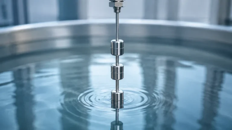
A standard configuration utilizes three electrodes of varying lengths, commonly designated as E1, E2, and E3:
1. E1 (High Level): The shortest electrode. When the liquid reaches this point, the circuit is completed to trigger a change in state (e.g., stopping a pump).
2. E2 (Low Level): The intermediate electrode. This provides the "hysteresis" or differential required to prevent the pump from rapidly cycling on and off (chattering) due to surface ripples.
3. E3 (Common/Ground): The longest electrode, which remains in contact with the liquid at all times to provide a return path for the sensing current.
By utilizing this three-wire logic, the floatless level switch 61f gp n can maintain a stable liquid level between the tips of E1 and E2.
Technical Specifications and Features
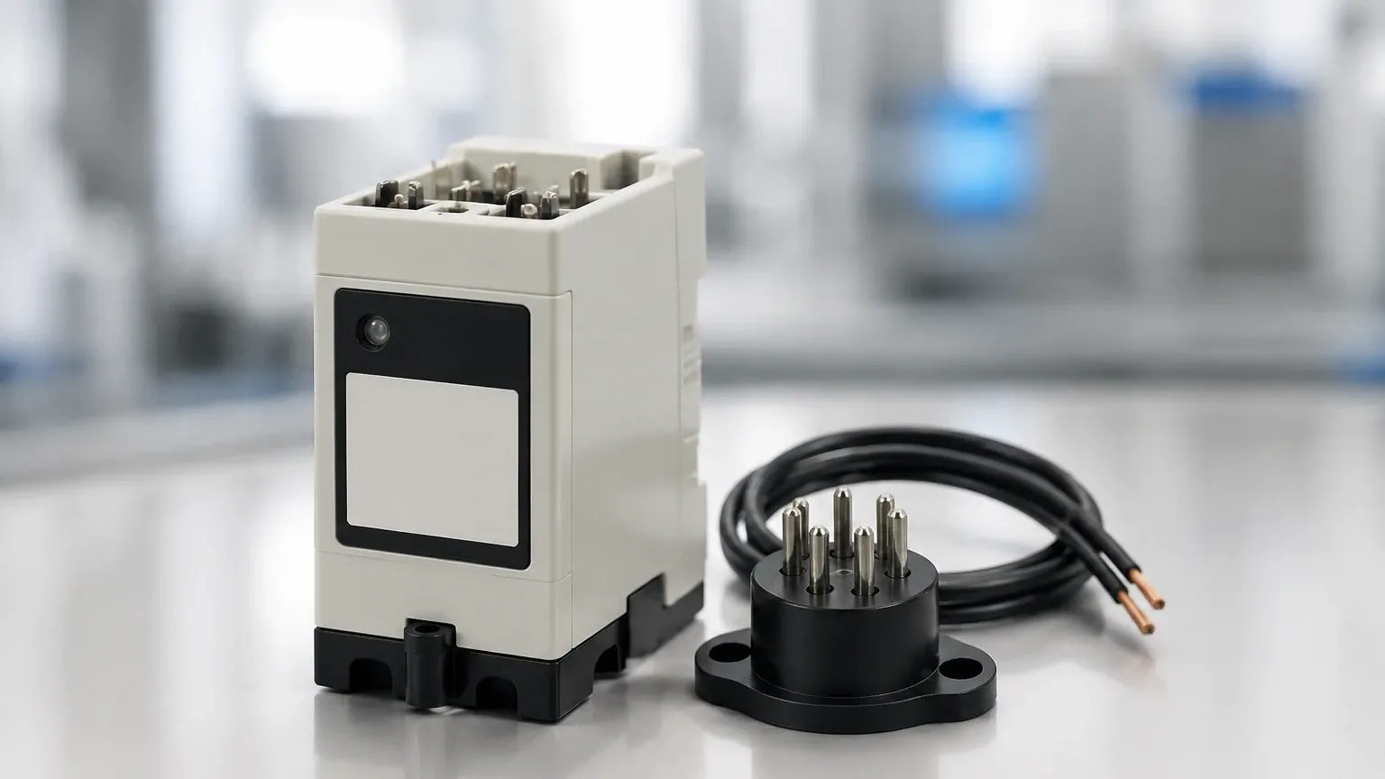
The 61F-GP-N is a plug-in type controller, designed for easy installation and replacement. It is typically mounted on a standard 8-pin circular socket (such as the PF083A).
Key Specifications
| Parameter | Standard Specification |
| :— | :— |
| Supply Voltage | 100V, 110V, 120V, 200V, 220V, 230V, or 240V AC; 50/60 Hz |
| Secondary Voltage | 8V AC (Standard) |
| Operate Resistance | 0 to approx. 4 kΩ (Standard type) |
| Release Resistance | Approx. 15 kΩ to ∞ (Standard type) |
| Response Time | Operate: 80 ms max; Release: 160 ms max |
| Control Output | 5 A at 250V AC (Resistive load) |
| Ambient Temperature | -10°C to 55°C |
| Ambient Humidity | 45% to 85% RH |
Compact Design
The "N" in the model name often denotes a compact version of the traditional 61F series. This smaller footprint allows for higher density in control panels, which is a critical requirement in modern industrial automation. Despite its small size, it maintains the same functional integrity as larger Level Switches in the conductive category.
Wiring and Logic Configurations
The floatless level switch 61f gp n can be wired for two primary types of operation: automatic water supply and automatic water drainage.
Automatic Water Supply
In this mode, the goal is to keep a tank filled. The relay is wired so that the pump starts when the liquid level drops below E2 and stops when the liquid level reaches E1.
- Wiring: The pump motor starter is connected to the Normally Closed (NC) contacts of the relay.
- Operation: When the tank is empty, the relay is de-energized, the NC contact is closed, and the pump runs. Once the water touches E1, the relay energizes, opening the NC contact and stopping the pump.
Automatic Water Drainage
This mode is used to prevent a tank or sump from overflowing. The pump starts when the liquid reaches E1 and stops when it drops below E2.
- Wiring: The pump motor starter is connected to the Normally Open (NO) contacts of the relay.
- Operation: When the water reaches E1, the relay energizes, closing the NO contact and starting the drainage pump. The pump continues to run until the level falls below E2, at which point the relay de-energizes and the pump stops.
Selection Criteria for Electrodes and Accessories
While the 61F-GP-N is the "brain" of the system, the choice of electrodes is equally important for long-term reliability. Electrodes must be selected based on the chemical compatibility of the liquid and the physical dimensions of the tank.
Electrode Materials
- SUS304/SUS316 Stainless Steel: The standard choice for clean water and mildly corrosive industrial water.
- Titanium or Hastelloy: Required for highly corrosive chemicals or acids where stainless steel would degrade quickly.
- Resin-Coated Electrodes: Used when the liquid is turbulent or when there is a risk of electrodes touching each other and creating a false signal.
Electrode Holders
Electrode holders secure the rods in place and provide insulation from the tank wall. For pressurized tanks, specialized hermetic holders are required to prevent leakage. For standard atmospheric tanks, simple plastic or ceramic holders are sufficient.
Practical Selection Table for Different Applications
| Application | Recommended Sensitivity | Electrode Material | Notes |
| :— | :— | :— | :— |
| Clean Water / Tap Water | Standard (4 kΩ) | SUS304 | Standard 8V secondary voltage. |
| High-Resistance Liquid | High-sensitivity (up to 1 MΩ) | SUS316 | Used for distilled water or pure water. |
| Long-Distance Wiring | Low-sensitivity | SUS304 | Reduces the effect of stray capacitance in long cables. |
| Waste Water / Sewage | Standard | SUS316 + Insulation | Use insulated rods to prevent debris from shorting. |
| High-Temperature Liquid | Standard | SUS316 | Requires high-temperature electrode holders. |
Installation Considerations and Best Practices
Proper installation is paramount to ensuring the floatless level switch 61f gp n functions without interference or false triggering.
1. Electrode Spacing: Maintain a minimum distance of 10 mm to 20 mm between electrodes to prevent bridging by debris or bubbles. In turbulent tanks, use a separator or a stilling well (a pipe surrounding the electrodes) to stabilize the liquid surface.
2. Wiring Length: The distance between the controller and the electrodes should be kept within the manufacturer's specified limits (typically 100 meters for standard models). Excessively long cables can introduce stray capacitance, leading to the controller failing to release when the liquid level drops.
3. Common Grounding: If the tank is made of an insulating material like plastic or fiberglass, the E3 (common) electrode must be used. If the tank is metal, the tank wall itself can sometimes serve as the common ground, though using a dedicated E3 rod is always recommended for better reliability.
4. Avoid Interference: Do not run electrode signal wires in the same conduit as high-voltage power lines. Electromagnetic interference can cause the sensitive relay to trip unexpectedly.
Limitations and Technology Comparisons
While the floatless level switch 61f gp n is highly effective, it is not a universal solution for all level measurement needs.
When to Use Conductive Switches
- Conductive liquids (water, milk, beer, acids, alkalis).
- Applications requiring simple on/off control.
- Budget-conscious projects where high-end radar or ultrasonic sensors are unnecessary.
When to Consider Alternatives
- Non-conductive Liquids: Conductive switches will not work with oils, fuels, or pure hydrocarbons. In these cases, a float switch or an ultrasonic sensor is required.
- Coating/Scaling Liquids: If the liquid leaves a heavy conductive residue (like thick sludge or metallic scaling), it can create a conductive bridge between electrodes even after the level has dropped. In such environments, a non-contact solution or a tuning fork level switch is preferable.
- Continuous Measurement: The 61F-GP-N provides point-level control (discrete levels). If you need to know the exact percentage of a tank's volume (e.g., 45% full), you must use a continuous transmitter such as a radar level meter or a hydrostatic pressure sensor.
Frequently Asked Questions (FAQ)
Q: Can I use the 61F-GP-N for oil level control?
A: No. Oil is a non-conductive dielectric fluid. The 61F-GP-N requires a conductive path to operate. For oil, consider a mechanical float switch or a capacitive level sensor.
Q: Why does my pump keep chattering even with three electrodes?
A: This is usually caused by a dirty E2 electrode or a loose connection. If the controller cannot "latch" the circuit between E1 and E2, it will lose the signal as soon as the water ripples away from E1. Check for scaling on the rods and ensure the wiring to E2 is secure.
Q: Is the 8V secondary voltage safe?
A: Yes, the secondary voltage applied to the electrodes is typically 8V AC, which is considered safe for humans and prevents significant electrolysis in the water.
Q: Can I cut the electrode rods to length?
A: Yes, stainless steel electrode rods are designed to be cut to the specific depths required by your tank. Ensure the ends are cleaned after cutting to maintain good electrical contact.
Conclusion
The floatless level switch 61f gp n remains a vital component in industrial fluid management due to its simplicity and lack of moving parts. By understanding the conductive principle and following strict installation guidelines regarding electrode placement and wiring, engineers can implement a highly reliable level control system. For applications involving non-conductive fluids or requiring high-precision continuous data, exploring the wider range of Level Switches and transmitters offered by professional manufacturers like Welk is recommended to ensure the optimal technology is matched to the specific process requirements.