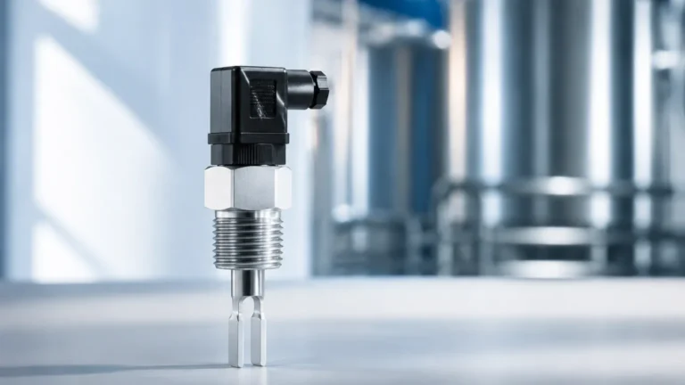
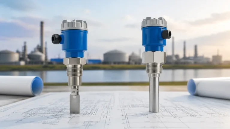
Governor Accumulator Oil Magnetic Level Switches
Governor Accumulator Oil Magnetic Level Switches
In the specialized field of hydroelectric power generation and large-scale industrial hydraulic systems, the governor system serves as the "brain" of the turbine, regulating speed and power output. At the heart of many high-pressure governor systems is the hydraulic accumulator—a pressure vessel designed to store energy in the form of pressurized oil and compressed gas (usually nitrogen). Monitoring the oil level within these accumulators is a critical safety and operational requirement. Governor accumulator oil magnetic level switches are the primary instruments used to ensure that the hydraulic fluid remains within specified limits to prevent system failure or equipment damage.
Measurement Principles of Magnetic Level Switches
To understand the application of governor accumulator oil magnetic level switches, it is essential to first examine the underlying physics of magnetic level detection. Unlike mechanical linkages that may leak under high pressure, magnetic switches utilize magnetic coupling to isolate the electrical components from the pressurized process fluid.
The Reed Switch Principle
The most common technology used in these devices is the magnetic reed switch. A reed switch consists of two ferromagnetic blades (reeds) hermetically sealed in a glass envelope. When a magnetic field—typically from a permanent magnet—is brought into proximity, the reeds become magnetized and attract each other, closing the circuit. When the magnet moves away, the reeds return to their original position due to their inherent elasticity, opening the circuit.
Float-Based Operation
In a governor accumulator application, a float containing a permanent magnet is placed inside the fluid chamber. As the oil level rises or falls, the float moves along a guide tube or within a bypass chamber. Stationary reed switches are positioned at specific setpoints (e.g., High-High, High, Low, Low-Low). When the magnetic float reaches the level of a switch, it triggers an electrical signal. This signal is then sent to the governor control cabinet to initiate alarms, start or stop hydraulic pumps, or trigger an emergency shutdown.
Magnetic Coupling in Bypass Indicators
For high-pressure accumulators, a bypass or "magnetic level gauge" configuration is often preferred. In this setup, a bypass pipe is connected to the side of the accumulator. A magnetic float moves inside this pipe. On the outside of the pipe, magnetic level switches are clamped at the desired heights. This design ensures that the electrical switches never come into contact with the high-pressure hydraulic oil, significantly increasing safety and ease of maintenance.
The Role of Level Switches in Governor Accumulators
Governor accumulators are typically "gas-over-oil" systems. The nitrogen gas provides the spring force, while the oil acts as the medium for the hydraulic work. The oil level must be precisely managed for several reasons:
1. Energy Storage Verification: If the oil level is too low, there may not be enough hydraulic volume to complete a full stroke of the turbine gates or blades during a power failure.
2. Pump Control: Level switches provide the start/stop logic for the oil pressure units (OPU) that keep the accumulator charged.
3. Aeration Prevention: If the oil level drops too far, nitrogen gas could enter the hydraulic lines, leading to cavitation, erratic governor behavior, and potential mechanical failure.
4. Overfill Protection: Excessive oil levels reduce the gas volume, which can lead to rapid pressure spikes and potential rupture or relief valve activation.
For engineers selecting Level Switches for these applications, the reliability of the magnetic coupling is paramount, as the environment often involves high-frequency vibrations and high-pressure cycles.
Technical Selection Criteria
Selecting the correct governor accumulator oil magnetic level switch requires a detailed analysis of the process conditions. Because hydraulic oil and high-pressure nitrogen environments are demanding, the following criteria must be evaluated:
Pressure and Temperature Ratings
Governor accumulators often operate at pressures ranging from 4.0 MPa (40 bar) to 20.0 MPa (200 bar) or higher. The float must be designed to withstand these pressures without collapsing. Stainless steel (316L) or titanium floats are standard. Temperature ratings typically range from -20°C to +80°C, though some industrial oils may run hotter during peak operation.
Fluid Density (Specific Gravity)
Standard hydraulic oils have a specific gravity (SG) typically between 0.85 and 0.92. The magnetic float must be calibrated to float in this specific range. If the float is too heavy, it will sink; if it is too light, it may not submerge enough to align the magnet with the external switch.
Electrical Output and Safety
Most governor systems require Single Pole Double Throw (SPDT) or Double Pole Double Throw (DPDT) contacts. In hazardous areas or specific power plant zones, explosion-proof (Ex d) or intrinsically safe (Ex i) ratings may be required for the switch housing.
Selection Table for Accumulator Level Switches
| Feature | Direct Insertion Switch | Bypass Magnetic Switch |
| :— | :— | :— |
| Pressure Range | Up to 10 MPa (Standard) | Up to 32 MPa (High Pressure) |
| Maintenance | Requires tank depressurization | Can be serviced while pressurized |
| Visibility | Switch only (No visual) | Integrated visual scale possible |
| Mounting | Top or Side Flange | Side-Side or Side-Bottom |
| Ideal For | Small, low-pressure tanks | Large, high-pressure accumulators |
Installation and Engineering Considerations
Proper installation is critical to the longevity and accuracy of governor accumulator oil magnetic level switches. Engineers should follow these practical guidelines:
Orientation and Alignment
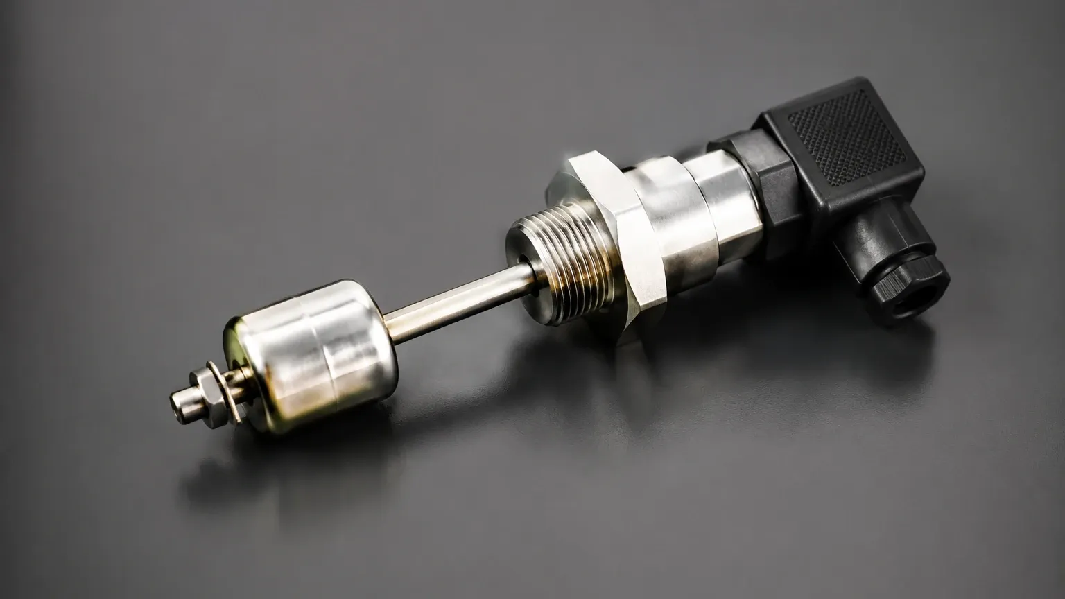
For bypass-style switches, the bypass chamber must be perfectly vertical. Any tilt can cause the float to rub against the chamber walls, leading to friction that prevents the float from following the oil level accurately. For direct insertion switches, ensure the guide rod is not bent during installation.
Turbulence and Stilling Wells
In systems where oil is frequently pumped in and out, the surface of the oil can become turbulent. This turbulence can cause the float to bounce, leading to "chattering" of the electrical contacts. In direct-insertion applications, a stilling well (a perforated pipe surrounding the float) should be used to dampen surface movement.
Magnetic Interference
Since these switches rely on magnetic fields, they should not be installed in close proximity to large electric motors, high-current cables, or other strong electromagnetic sources. Ferromagnetic structures (like heavy steel beams) should be at least 100mm away from the magnetic switch to avoid distorting the magnetic field.
Wiring and Protection
Use shielded cables to prevent electrical noise from interfering with the governor control signals. It is also recommended to use a relay in the control cabinet to handle the actual load of the pumps or valves, rather than running high current directly through the delicate reed switches.
Limitations and Maintenance
While magnetic level switches are robust, they are not without limitations. Understanding these boundaries helps in designing a more resilient system.
* Ferrous Contamination: Hydraulic systems can accumulate fine iron particles over time due to wear on pumps and valves. These particles can stick to the magnetic float, eventually making it too heavy or causing it to jam. Regular oil filtration and the use of magnetic traps in the hydraulic circuit are essential.
* Mechanical Wear: Although reed switches are rated for millions of cycles, mechanical vibration from the turbine can eventually cause fatigue in the glass envelope or the reeds themselves. Periodic testing of the alarm setpoints is a mandatory maintenance task.
* Viscosity Changes: In extremely cold climates, hydraulic oil viscosity increases significantly. This can slow the response time of the float. If the plant is subject to cold starts, tank heaters or trace heating on the bypass chamber may be necessary.
Frequently Asked Questions (FAQs)
Q1: Can I use a standard water level switch for governor oil?
No. Hydraulic oil has a lower density than water (approx. 0.88 vs 1.0). A float designed for water will sit lower in oil or may not float at all. Additionally, the materials must be compatible with hydraulic fluid to prevent seal degradation.
Q2: How do I test the switch without draining the accumulator?
For bypass-style switches, you can use an external testing magnet. By sliding a strong magnet along the outside of the chamber, you can manually lift the internal float (if the system is depressurized) or simply trigger the external switch contacts to verify the wiring and control logic.
Q3: What is the advantage of a magnetic switch over an ultrasonic sensor in an accumulator?
Ultrasonic sensors struggle with high-pressure gas environments because the speed of sound changes with gas pressure and composition. Magnetic switches are purely mechanical/magnetic and are unaffected by the pressure or density of the nitrogen gas above the oil.
Q4: Are these switches suitable for SIL-rated safety loops?
Yes, many magnetic level switches are designed for use in Functional Safety systems and can be provided with SIL 2 or SIL 3 certification, which is often required for modern hydroelectric governor protection schemes.
Conclusion
Governor accumulator oil magnetic level switches are indispensable components in the hydropower and heavy hydraulic industries. By utilizing the simple yet effective principle of magnetic coupling, these devices provide reliable, high-pressure level monitoring that protects critical infrastructure. When selecting a switch, engineers must prioritize pressure ratings, fluid density compatibility, and the specific requirements of the governor control logic to ensure long-term operational stability. Regular maintenance, particularly monitoring for oil cleanliness and ferrous debris, remains the best practice for ensuring these switches perform their safety-critical functions when needed.
Download Governor Accumulator Oil Magnetic Level Switches as a PDF