Level Sensor Arduino
Level Sensor Arduino
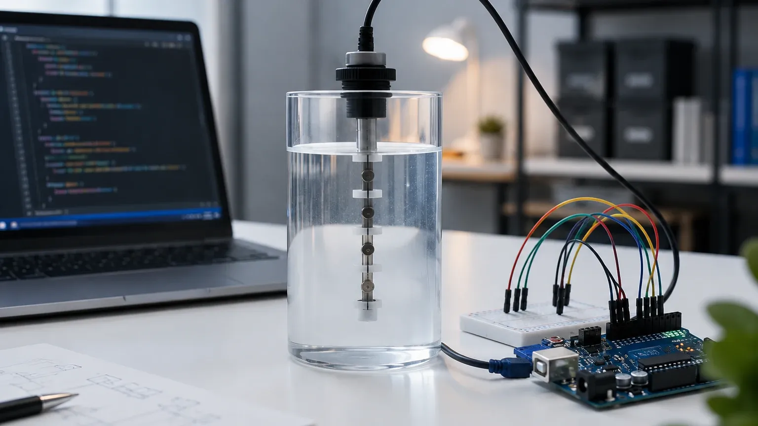
In the realm of industrial automation and process control, the ability to monitor liquid levels accurately is fundamental. While professional-grade instrumentation is the standard for final deployment, many engineering teams and developers utilize the Arduino ecosystem for rapid prototyping, proof-of-concept testing, and low-cost monitoring solutions. Integrating a level sensor with an Arduino allows for the development of customized logic, data logging, and remote monitoring systems before transitioning to robust industrial Level Switches and continuous measurement transmitters.
Understanding the underlying measurement principles is essential for selecting the right technology, whether you are building a simple sump pump controller or a complex chemical inventory system. This guide explores the various technologies compatible with the Arduino platform and how they scale to industrial applications.
Core Measurement Principles
Before selecting hardware, it is vital to understand how different sensors interact with the media they measure. Level sensing generally falls into two categories: point-level detection (on/off) and continuous level measurement.
1. Ultrasonic Time-of-Flight
Ultrasonic sensors are among the most popular choices for Arduino-based projects. These sensors emit a high-frequency sound pulse (typically 40 kHz) and measure the time it takes for the echo to return from the liquid surface.
* Principle: The distance is calculated using the speed of sound in air (approximately 343 m/s at 20°C). The formula used is: $Distance = (Time \times Speed\ of\ Sound) / 2$.
* Arduino Integration: Most modules, like the HC-SR04 or the waterproof JSN-SR04T, use a simple trigger and echo pin configuration. The Arduino measures the duration of the high pulse on the echo pin using the `pulseIn()` function.
2. Hydrostatic Pressure
Hydrostatic level sensors measure the pressure exerted by a liquid column at a specific depth. This method is highly effective for deep tanks or wells where ultrasonic signals might be obstructed.
* Principle: Pressure is directly proportional to the height of the liquid ($P = \rho gh$). By measuring the pressure at the bottom of the tank and knowing the density of the fluid, the level can be determined with high precision.
* Arduino Integration: These sensors often output a 4-20mA or 0-5V signal. For Arduino, a 0-5V signal can be read directly via an Analog-to-Digital Converter (ADC) pin, while 4-20mA signals require a precision resistor (typically 250 ohms) to convert the current into a readable voltage (1-5V).
3. Capacitive Sensing
Capacitive level sensors detect changes in electrical capacitance caused by the presence of a liquid.
* Principle: The sensor acts as one plate of a capacitor, and the liquid (or the tank wall) acts as the dielectric or the second plate. As the level rises, the capacitance increases.
* Arduino Integration: Capacitive sensors can often detect liquid through non-metallic tank walls (like plastic or glass), making them ideal for non-contact applications. They usually provide a digital output for point-level detection or an I2C interface for continuous measurement.
4. Optical Refraction
Optical sensors are used primarily for point-level detection. They consist of an infrared LED and a phototransistor housed within a clear plastic dome.
* Principle: When the sensor tip is in the air, the IR light reflects internally within the dome back to the receiver. When submerged in liquid, the light refracts into the fluid, and the receiver detects a drop in light intensity.
* Arduino Integration: These are typically treated as digital switches, returning a HIGH or LOW signal to the Arduino when the liquid reaches the sensor tip.
Selection Criteria for Level Measurement
Choosing the right level sensor for an Arduino project depends on the physical properties of the liquid, the container geometry, and the environmental conditions. The following table provides a comparison of common technologies.
| Sensor Type | Best Application | Accuracy | Max Range | Limitations |
| :— | :— | :— | :— | :— |
| Ultrasonic | Water tanks, open channels | ±3 mm | 0.02 m to 4.5 m | Affected by foam, steam, and heavy dust. |
| Hydrostatic | Deep wells, fuel tanks | High (0.5% FS) | Up to 200 m+ | Requires sensor immersion; density must be constant. |
| Capacitive | Non-contact plastic tanks | Moderate | Point or short range | Sensitive to coating/buildup on the tank wall. |
| Optical | Leak detection, small vessels | Very High | Point detection | Not suitable for liquids that crystalize or stain. |
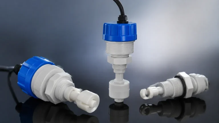
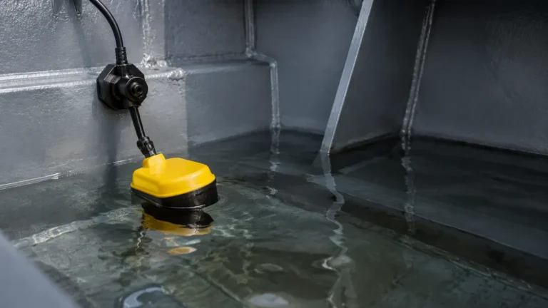
| Float Switch | Overflow/Low-level alarms | Discrete | Point detection | Moving parts can jam in viscous or dirty fluids. |
| Radar (Industrial) | Chemical processing, silos | ±1 mm | Up to 70 m | Higher cost; usually requires RS485/Modbus for Arduino. |
Practical Arduino Implementation
When interfacing these sensors with an Arduino, several engineering factors must be considered to ensure data reliability and system longevity.
Signal Conditioning and Filtering
Raw data from sensors, especially ultrasonic and hydrostatic types, can be noisy. Implementing a moving average filter in the Arduino sketch is a standard practice. By taking 10 to 20 readings and averaging them, you can eliminate outliers caused by surface ripples or electrical interference.
Power Management
Many industrial-grade sensors require 12V or 24V DC power, whereas an Arduino typically operates at 5V or 3.3V. When using a 24V hydrostatic transmitter, ensure the sensor and the Arduino share a common ground, and use a voltage divider or an industrial signal isolator to protect the Arduino's input pins.
Calibration
Calibration is the process of mapping the raw sensor output (e.g., an ADC value from 0 to 1023) to a physical unit (e.g., centimeters or liters). For a linear sensor like a hydrostatic transmitter, the `map()` function in Arduino can be used, though floating-point math is often preferred for higher precision:
`float level = (analogValue – offset) * scaleFactor;`
Installation Considerations
Correct physical installation is as important as the code itself. Even the most advanced sensor will fail if placed incorrectly.
1. Dead Zones (Blocking Distance): Ultrasonic sensors have a minimum distance (usually 2 cm to 20 cm) where they cannot measure accurately. Ensure the sensor is mounted high enough above the maximum possible liquid level to account for this.
2. Tank Geometry: Avoid placing sensors near the center of a circular tank if using ultrasonic or radar, as the walls can create focal points for echoes. Similarly, stay away from inlet pipes where turbulence and splashing occur.
3. Environmental Protection: For outdoor or industrial environments, use sensors with appropriate Ingress Protection (IP) ratings. A JSN-SR04T is rated IP67, making it suitable for damp environments, whereas a standard HC-SR04 is only for indoor bench testing.
4. Cable Runs: Long cable runs between the sensor and the Arduino can lead to voltage drops and electromagnetic interference (EMI). Use shielded twisted-pair cables for analog signals and consider using RS485 communication for distances exceeding 10 meters.
From Prototyping to Industrial Reality
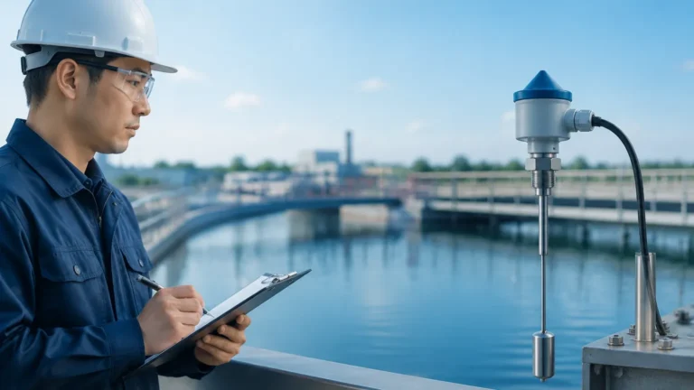
While an Arduino-based system is excellent for development, industrial environments often demand higher reliability, certifications (like ATEX for explosive atmospheres), and integration with PLC (Programmable Logic Controller) systems.
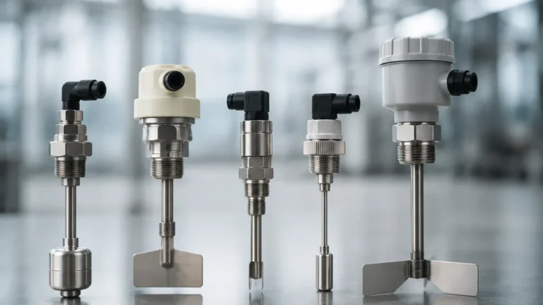
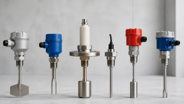
When moving from a prototype to a permanent installation, engineers often replace hobbyist modules with professional Level Switches or radar level meters. These industrial units provide:
* Enhanced Durability: Stainless steel or PTFE housings that resist corrosion.
* Standardized Outputs: 4-20mA, HART, or Modbus RTU protocols that are native to industrial control networks.
* Advanced Signal Processing: Built-in algorithms to ignore agitators, internal tank structures, and foam.
Frequently Asked Questions
Q: Can I use an Arduino level sensor for gasoline or flammable liquids?
A: Standard hobbyist sensors and Arduino boards are not intrinsically safe. For flammable liquids, you must use sensors with ATEX or IECEx certification and appropriate Zener barriers to prevent sparks. Industrial magnetic level gauges or specialized hydrostatic transmitters are recommended for these applications.
Q: How do I measure the level of a corrosive chemical with Arduino?
A: Use non-contact methods like ultrasonic or capacitive sensors. If the sensor must touch the liquid, ensure it is made of compatible materials like PVDF, PP, or PTFE. Always check a chemical compatibility chart before selection.
Q: Why is my ultrasonic sensor giving erratic readings?
A: This is often caused by "ghost echoes" from the tank walls, steam condensing on the sensor face, or the liquid surface being too turbulent. Try adding a stilling well (a vertical pipe in which the sensor is mounted) to provide a smooth surface for measurement.
Q: Can Arduino handle multiple level sensors?
A: Yes, using I2C multiplexers or multiple analog/digital pins, an Arduino can monitor several tanks simultaneously. However, ensure the power supply can handle the total current draw of all connected sensors.
Conclusion
Using a level sensor with an Arduino is a powerful way to understand the dynamics of fluid measurement and develop custom logic for specific applications. By selecting the appropriate measurement principle—whether ultrasonic for non-contact, hydrostatic for depth, or optical for point detection—developers can create effective monitoring solutions. As projects scale in complexity and environmental rigor, transitioning to professional-grade instruments ensures the long-term reliability and safety required in B2B and industrial sectors.