Fuel Level Switches
Fuel Level Switches
In industrial fuel management, precise point-level detection is essential for operational safety, environmental compliance, and inventory control. Fuel level switches serve as the primary line of defense against tank overfills and the critical indicator for low-level conditions that could lead to pump cavitation or generator failure. Whether managing diesel for backup power, kerosene for heating, or specialized aviation fuels, selecting the correct switching technology requires a deep understanding of fluid properties, tank dynamics, and hazardous area requirements.
As a specialized engineering component, Level Switches must be integrated into control systems to trigger alarms, start or stop pumps, and interface with Emergency Power Off (EPO) systems. This guide examines the technical principles, selection criteria, and installation best practices for fuel level switches in industrial B2B applications.
Measurement Principles for Fuel Level Switches
Fuel level switches operate on various physical principles, each offering distinct advantages depending on the fuel type and the storage environment. Understanding these principles is the first step in engineering a reliable level control system.
Float-Operated Magnetic Switches
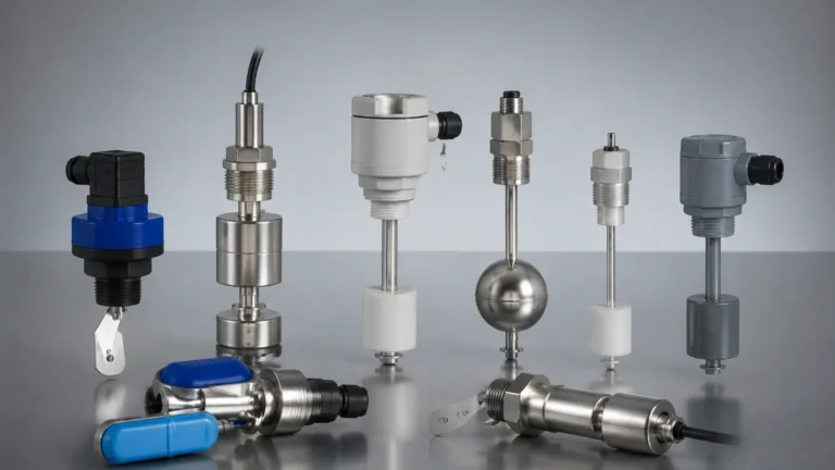
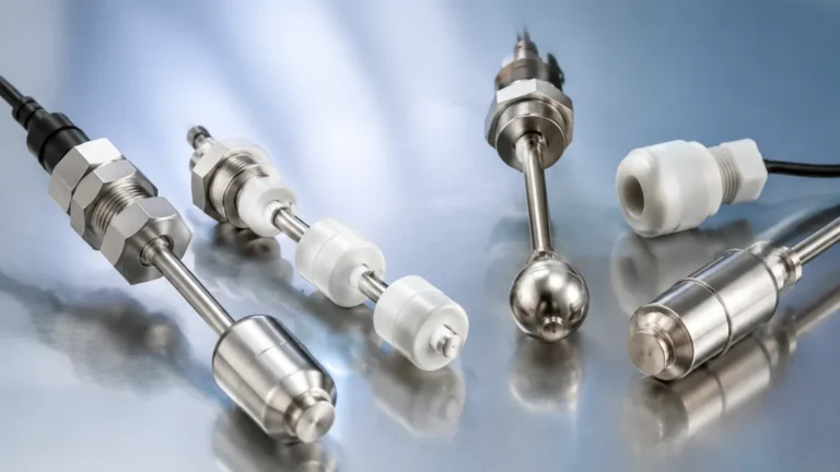
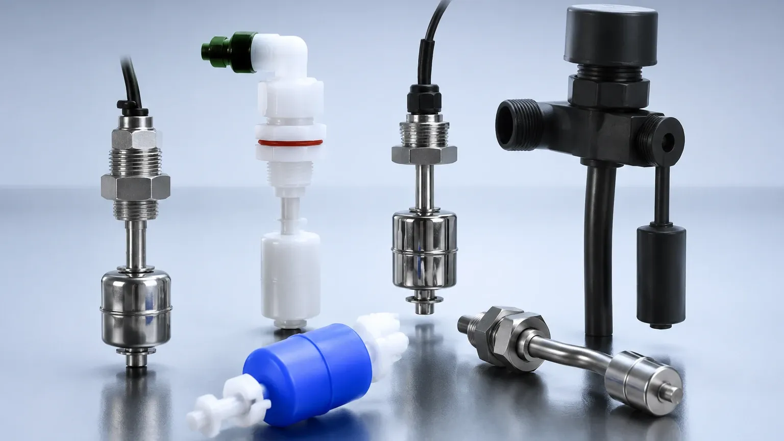
This is the most common technology for clean fuel applications. A float containing an internal magnet moves vertically along a stem as the fuel level rises or falls. Inside the stationary stem, one or more reed switches are positioned at specific set points. When the float’s magnetic field aligns with the reed switch, the circuit closes (or opens), sending a signal to the controller.
* Advantages: Simple design, requires no external power to operate the switch itself, and is relatively low-cost.
* Limitations: Moving parts can become stuck if the fuel contains heavy paraffin wax or contaminants. They are also sensitive to high-turbulence environments.
Vibrating Tuning Fork Switches
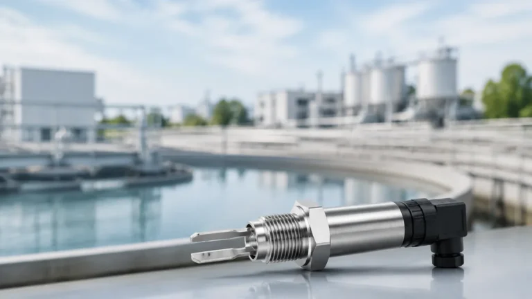
The vibrating level switch utilizes a tuning fork-shaped sensing element driven by internal piezoelectric crystals. The fork vibrates at its natural resonant frequency in the air. When the fuel reaches the fork and submerges it, the frequency changes due to the increased density of the medium. The electronics detect this shift and actuate the output.
* Advantages: Highly resistant to turbulence and bubbles; requires no calibration; no moving parts to wear out.
* Limitations: Higher initial cost than basic float switches; requires a power supply to drive the electronics.
Capacitance Level Switches
Capacitance switches treat the sensor probe and the tank wall (or a reference electrode) as two plates of a capacitor. Fuels, being hydrocarbons, typically have a low dielectric constant ($ε_r ≈ 2.0$ to $2.2$). As the fuel replaces the air surrounding the probe, the capacitance of the system changes. The switch detects this change and triggers the relay.
* Advantages: Excellent for high-temperature and high-pressure fuel systems; no moving parts.
* Limitations: Requires calibration for the specific fuel type; accuracy can be affected if the fuel composition (and thus the dielectric constant) changes significantly.
Optical Level Switches
Optical sensors use an infrared LED and a light receiver housed within a glass or plastic prism. When the sensor is in the air, the IR light reflects internally within the prism back to the receiver. When submerged in fuel, the light refracts into the liquid, causing the receiver to lose the signal and trigger the switch.
* Advantages: Extremely compact; ideal for tight spaces and small fuel lines.
* Limitations: Can be affected by heavy coating or extremely dark, opaque fuels if the prism becomes fouled.
Technical Selection Criteria
When specifying fuel level switches, engineers must evaluate several variables to ensure long-term reliability. Misalignment between the switch technology and the application can lead to false alarms or, more critically, a failure to actuate during an overfill event.
1. Fuel Type and Chemical Compatibility
Different fuels have varying chemical properties. Diesel and heavy fuel oils (HFO) are relatively stable, but biofuels and certain additives can be corrosive to standard elastomers. Stainless steel (304 or 316L) is the industry standard for wetted parts in fuel systems. For seals and O-rings, Viton (FKM) is generally preferred over Nitrile (NBR) due to its superior resistance to a wider range of hydrocarbons.
2. Operating Environment (Temperature and Pressure)
Fuel storage tanks are often vented to the atmosphere, meaning pressure requirements are low. However, in pressurized fuel delivery lines or high-altitude storage, the switch must be rated for the maximum system pressure. Standard industrial fuel switches are typically rated for up to 10 bar (145 psi), though high-pressure versions exceeding 40 bar are available.
3. Hazardous Area Certifications
Since most fuels are flammable, the level switch must comply with safety standards for explosive atmospheres. In many jurisdictions, this requires ATEX (Europe), IECEx (Global), or UL/CSA (North America) certifications. Switches must be either "Intrinsically Safe" (requiring a safety barrier) or "Explosion-Proof/Flame-Proof" (housed in a heavy-duty enclosure designed to contain an internal explosion).
Selection Table: Fuel Level Switch Technologies
| Technology | Typical Application | Max Temp (Approx.) | Max Pressure | Viscosity Limit | Dielectric Sensitivity |
| :— | :— | :— | :— | :— | :— |
| Magnetic Float | Diesel Day Tanks | 120°C | 20 bar | < 500 cSt | None |
| Tuning Fork | Bulk Fuel Storage | 150°C | 40 bar | < 10,000 cSt | None |
| Capacitance | High-Temp Fuel Oil | 200°C+ | 60 bar | < 2,000 cSt | High |
| Optical | Leak Detection Sumps | 80°C | 10 bar | < 100 cSt | None |
Installation Considerations
Proper installation is as critical as selecting the right technology. Most fuel level switch failures are the result of poor placement or incorrect wiring rather than mechanical failure of the instrument itself.
Orientation and Positioning
* Vertical vs. Horizontal: Float switches are often mounted vertically from the top of the tank, while tuning forks and optical switches can be mounted horizontally through the side wall. If side-mounting, ensure the switch is positioned away from the fuel inlet to avoid false triggers from splashing fuel.
* Still Wells: In tanks with high turbulence or internal agitators, float-type fuel level switches should be installed inside a still well (a pipe with vent holes). This stabilizes the liquid surface around the float and protects the stem from mechanical stress.
Electrical and Wiring
* Contact Protection: Reed switches used in float-type sensors are sensitive to inductive loads (like motor starters or large relays). Always use a secondary interposing relay or a protection circuit (RC snubbers for AC, diodes for DC) to prevent the contacts from welding shut.
* Cable Entry: For outdoor fuel tanks, ensure that cable entries point downward or use a drip loop to prevent rainwater from migrating into the switch housing via the conduit.
Calibration and Testing
While tuning fork and float switches are often "plug-and-play," capacitance switches require a dry-tank and wet-tank calibration. Regardless of the technology, a functional "wet test" should be performed during commissioning to verify that the control system responds correctly to the switch state change.
Limitations and Common Risks
While fuel level switches are robust, they are not universal solutions. Engineers should be aware of the following limitations:
1. Paraffin Buildup: In cold climates, diesel fuel can reach its "cloud point," where paraffin wax begins to precipitate. This wax can coat floats or tuning forks. In such cases, heated enclosures or self-cleaning tuning forks may be required.
2. Tank Sludge: Over time, bulk fuel tanks accumulate a layer of water and sludge at the bottom. Low-level switches must be positioned high enough to avoid being submerged in this debris, which can foul the sensing element.
3. Foaming: High-speed fuel filling can create foam on the surface. Some technologies, like ultrasonic or optical switches, may struggle to distinguish between the liquid surface and the foam layer. Tuning forks are generally the most reliable in foaming conditions.
Maintenance and Troubleshooting
A proactive maintenance schedule ensures that fuel level switches remain operational for their intended service life, which often exceeds 10 years in clean fuel applications.
* Annual Inspection: Visually inspect the switch for signs of corrosion or mechanical damage. For float switches, manually move the float to ensure it slides freely along the stem.
* Continuity Testing: Use a multimeter to verify the switch state. A "normally closed" (NC) switch should show near-zero resistance when not actuated. If the resistance is high, the internal contacts may be pitted or oxidized.
* Cleaning: If the fuel quality is poor, remove the switch periodically to clean the sensing element. Use a solvent compatible with the switch materials (e.g., isopropyl alcohol for stainless steel parts).
Frequently Asked Questions (FAQ)
Q: Can I use a water level switch for diesel fuel?
A: Not necessarily. While the mechanical principle is the same, the density of diesel (≈ 0.85 g/cm³) is lower than water (1.0 g/cm³). A float designed for water may not be buoyant enough to rise in diesel. Always specify the specific gravity (SG) of the fuel when ordering float-type switches.
Q: What is the difference between a "Normally Open" and "Normally Closed" configuration in fuel systems?
A: For high-level alarms (overfill prevention), it is best practice to use a "Normally Closed" (NC) circuit that opens on alarm. This provides a fail-safe: if a wire breaks or power is lost, the system interprets it as an alarm state, preventing a potential overfill.
Q: Are fuel level switches compatible with biodiesel?
A: Biodiesel (FAME) is more chemically aggressive than petroleum diesel. Ensure that all elastomers (seals) are made of Viton (FKM) or PTFE, as standard Nitrile (Buna-N) seals may swell and fail when exposed to high concentrations of biodiesel.
Q: How do I prevent false alarms caused by tank vibrations?
A: If the tank is connected to a large generator or pump that causes significant vibration, use a tuning fork switch with a programmable delay (e.g., 1–3 seconds). This ensures the switch only triggers if the level change is sustained, ignoring momentary splashes or vibrations.
By carefully matching the switching technology to the specific fuel properties and environmental conditions, facility managers can ensure reliable, long-term performance. For more information on selecting the right instrument for your project, you can explore the various industrial Level Switches designed for high-accuracy fuel and oil applications.