Level 5 Switch
Level 5 Switch
In industrial process control, the term "level 5 switch" typically refers to a multi-point level detection system capable of monitoring five distinct liquid or solid levels within a single vessel. While single-point switches are sufficient for simple overflow protection, complex automation workflows—such as those found in chemical processing, water treatment, and oil refineries—require more granular data. A level 5 switch configuration allows engineers to manage pump activation, deactivation, and multi-stage safety alarms (High-High, High, Low, Low-Low) through a single process connection.
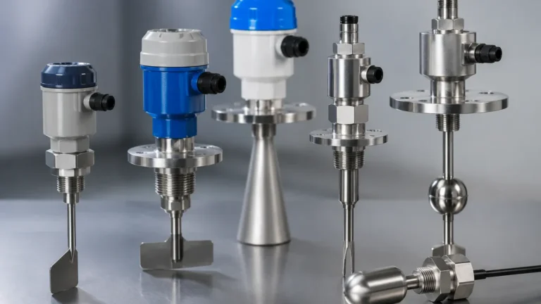
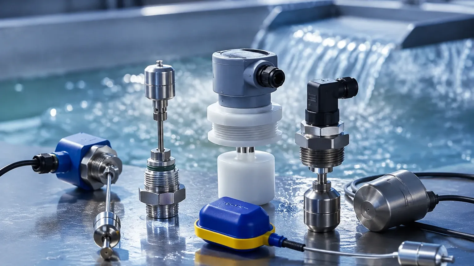
Selecting the correct technology for a Level Switches application involves understanding the physical properties of the media and the mechanical constraints of the tank. This guide examines the measurement principles, selection criteria, and installation best practices for multi-point level detection systems.
Measurement Principles of Multi-Point Level Switches
Before selecting a specific model, it is essential to understand how different technologies achieve multi-point detection. For a "level 5" requirement, the hardware must either support five independent sensing elements on a single probe or utilize a continuous measurement technology with five programmed switching outputs.
Magnetic Float Principle
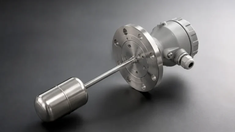
This is the most common method for multi-point liquid level detection. A hollow stem contains five sets of reed switches at predetermined heights. A permanent magnet is housed within a float that slides up and down the stem as the liquid level changes. When the magnet aligns with a reed switch, the circuit closes (or opens), triggering a signal. This method is highly reliable for clean liquids and does not require external power for the sensing element itself.
Vibrating Tuning Fork Principle
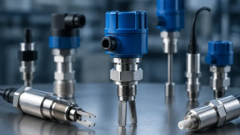
While typically used for single-point detection, multiple tuning fork switches can be installed at different heights, or a specialized multi-sensor array can be utilized. The sensor vibrates at its natural resonant frequency in air. When the media covers the fork, the frequency drops, which is detected by the internal electronics. This technology is excellent for detecting powders, granules, and liquids with varying densities.
Capacitance Principle
Capacitance level switches measure the change in electrical capacitance between the sensing electrode and the tank wall (or a reference electrode). As the media rises, the dielectric constant changes, altering the capacitance. Multi-point capacitance switches use segmented probes to identify five distinct levels. This is particularly effective in corrosive environments where moving parts, like floats, might fail.
Ultrasonic and Radar (Point Level Simulation)
In some advanced "level 5" configurations, a continuous level transmitter (such as a radar or ultrasonic sensor) is paired with a multi-channel controller. The controller is programmed with five set-points. When the continuous reading hits a specific threshold, the controller triggers a physical relay. This provides the functionality of five switches without requiring five physical sensors in the media.
Key Evaluation Criteria for Level 5 Switches
When specifying a level 5 switch for an industrial project, the following parameters must be confirmed to ensure long-term accuracy and safety.
1. Media Compatibility
The chemical composition of the fluid or solid is the primary factor. For corrosive chemicals, PVDF, PTFE, or high-grade stainless steel (316L) probes are required. For food and beverage applications, sanitary connections and polished surfaces are mandatory to prevent bacterial growth.
2. Operating Temperature and Pressure
Standard magnetic float switches are often rated up to 100°C (212°F) and 10 bar (145 psi). However, high-pressure steam applications or cryogenic storage require specialized bellows or high-temperature alloys. Always verify that the switch housing and seals (O-rings) can withstand the maximum possible process pressure.
3. Media Density and Viscosity
For float-based level 5 switches, the float must be lighter than the liquid's minimum density (Specific Gravity). If the liquid is highly viscous or prone to crystallization, mechanical floats may stick. In these cases, non-contacting or vibrating technologies are preferred.
4. Switch Logic and Output
Engineers must determine if the application requires Normally Open (NO) or Normally Closed (NC) contacts. For safety-critical systems, NC is often preferred because a wire break will trigger an alarm state (fail-safe). Multi-point switches usually output via a terminal box or a multi-pin connector.
Technology Selection Table
| Technology | Suitable Media | Max Points | Pressure Resistance | Maintenance Level |
| :— | :— | :— | :— | :— |
| Magnetic Float | Clean Liquids | Up to 7+ | Moderate (up to 40 bar) | Low |
| Tuning Fork | Liquids/Solids | Usually 1 per unit | High (up to 64 bar) | Very Low |
| Capacitance | Acids/Alkalis | Variable | High | Moderate |
| Conductivity | Conductive Liquids | Up to 5 | Low | Low |
| Optical | Clear Liquids | Variable | Moderate | High (Cleaning required) |
Practical Application: The 5-Point Configuration Logic
In a standard industrial tank, the five points of a level 5 switch are typically assigned the following roles:
1. Level 1 (Low-Low): Emergency shutdown. Prevents pump cavitation or dry-running of heaters.
2. Level 2 (Low): Pump Start. Signals the system to begin filling the tank.
3. Level 3 (Mid/Control): Process monitoring. Often used to trigger a secondary feed or a chemical dose.
4. Level 4 (High): Pump Stop. Signals the fill valve to close or the supply pump to cease operation.
5. Level 5 (High-High): Overfill protection. Triggers an audible alarm or an emergency block valve.
Installation Considerations and Best Practices
Proper installation is as critical as sensor selection. Even the most advanced level 5 switch will fail if placed in a turbulent or obstructed area of the tank.
* Avoid Turbulence: Do not install the switch directly under a fill pipe. The force of the incoming liquid can damage the probe or cause "chatter" (rapid cycling) of the switches. If turbulence is unavoidable, use a stilling well (a bypass pipe) to stabilize the liquid surface.
* Vertical Alignment: For float-based multi-point switches, the stem must be installed within ±5° of vertical. Significant tilting increases friction between the float and the stem, leading to inaccurate readings or mechanical sticking.
* Proximity to Metal: For capacitance and ultrasonic switches, ensure the sensor is not too close to the tank wall or internal baffles, as this can cause false positives due to interference or signal reflection.
* Wiring and Grounding: Use shielded cables to prevent electromagnetic interference (EMI) from nearby motors or variable frequency drives (VFDs) from affecting the signal. Ensure the instrument is properly grounded to the tank or a dedicated earth ground.
* Insertion Length: When ordering a level 5 switch, the insertion length (L) and the exact distance for each of the five set points must be specified. These are typically measured from the bottom of the mounting flange or thread.
Limitations and Potential Risks
While highly effective, level 5 switches have specific limitations that operators must manage:
* Coating and Buildup: In applications involving wastewater or viscous oils, material can build up on the probe. For float switches, this may prevent the float from moving. For capacitance switches, it can change the dielectric reading. Regular cleaning schedules are necessary in these environments.
* Mechanical Wear: Any system with moving parts (like floats) will eventually experience mechanical wear. In high-cycle applications, non-contacting switches or vibrating forks may offer a longer service life.
* Specific Gravity Changes: If a tank is used for different liquids with significantly different densities, a float calibrated for a heavy liquid might not rise in a lighter liquid.
Maintenance Guidance
To ensure the reliability of a level 5 switch, a preventative maintenance program should include:
1. Visual Inspection: Check for corrosion on the housing and ensure the cable entry is sealed against moisture.
2. Functional Test: Manually move the float (if possible) or change the liquid level to verify that all five relays trigger at the correct heights.
3. Cleaning: Remove any scale or debris from the probe or sensing element using a compatible solvent.
4. Terminal Check: Ensure all electrical connections remain tight and free of oxidation.
Frequently Asked Questions (FAQs)
Q: Can I change the set points of a level 5 float switch after installation?
A: For most magnetic reed switches, the set points are fixed during manufacturing and cannot be moved easily. If adjustability is required, consider a system using five individual switches or a continuous level sensor with a programmable controller.
Q: What is the maximum length for a multi-point level switch probe?
A: Welk and other professional manufacturers can produce probes up to 6 meters (approx. 20 feet) in length. However, for lengths exceeding 2 meters, support brackets or stilling wells are recommended to prevent the probe from swaying due to liquid movement.
Q: Is a level 5 switch suitable for hazardous (Ex) zones?
A: Yes, but the switch must be rated for the specific zone (e.g., ATEX or IECEx). This usually involves using an intrinsically safe (IS) barrier or an explosion-proof housing.
Q: How do I handle foaming liquids with a level 5 switch?
A: Foam can cause false triggers in ultrasonic and some capacitance switches. Magnetic float switches are generally unaffected by foam, as the float reacts only to the liquid's density. Alternatively, a tuning fork switch with adjusted sensitivity can be used.
For engineers and procurement specialists seeking reliable automation components, choosing the right Level Switches is a balance of application requirements and budget. By consolidating five detection points into a single device, facilities can reduce installation costs, minimize tank penetrations, and improve overall system safety.