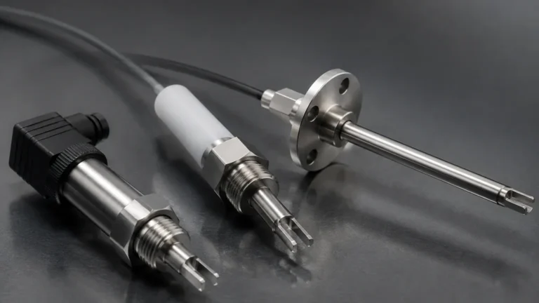
Level Switch 4 20ma
Level Switch 4 20ma
In the landscape of industrial automation, the term "level switch 4 20ma" represents a critical bridge between discrete point detection and continuous process monitoring. Traditionally, Level Switches were simple mechanical or electronic devices designed to provide an on/off signal at a specific height. However, modern process requirements often demand the precision of a 4-20mA analog signal to allow for variable setpoints, remote diagnostics, and real-time data logging. This article examines the principles, technologies, and selection criteria for devices that combine switching logic with analog output.
Understanding the Level Switch 4 20ma Concept
To understand a level switch 4 20ma, one must distinguish between a standard switch and a level transmitter. A traditional switch uses a relay or transistor output to signal that a liquid has reached a specific point (High or Low). A 4-20mA device, conversely, is technically a continuous level transmitter.
When engineers search for a "level switch 4 20ma," they are typically looking for one of two things:
1. A hybrid electronic level switch: A device that features a local display and integrated relay outputs but also provides a 4-20mA signal for the control system.
2. A continuous transmitter used for switching: Using a radar, ultrasonic, or hydrostatic sensor to send a constant signal to a Programmable Logic Controller (PLC), where software-defined "virtual switches" trigger alarms or pumps.
The 4-20mA current loop is the industry standard because of its robustness against electrical noise and its ability to travel over long distances without signal degradation. In this configuration, 4mA typically represents 0% (empty) and 20mA represents 100% (full). A current below 4mA (usually around 3.6mA or 3.8mA) often indicates a sensor fault, providing a fail-safe mechanism that simple mechanical switches lack.
Measurement Principles and Signal Conversion
Before selecting a device, it is essential to understand how physical level changes are converted into a 4-20mA signal. Welk utilizes several core technologies to achieve this conversion, each suited to different media and environmental conditions.
Hydrostatic Pressure Principle
Hydrostatic level transmitters measure the pressure exerted by a liquid column. The principle is based on the formula:
P = ρgh
*(Where P is pressure, ρ is liquid density, g is gravity, and h is the height of the liquid).*
The sensor's diaphragm converts this mechanical pressure into an electrical signal, which the internal electronics scale to a 4-20mA output. For example, in a 10-meter tank, 0 meters would output 4mA, and 10 meters would output 20mA. If the system requires a switch at 8 meters, the PLC is programmed to trigger a relay when the loop current reaches 16.8mA.
Ultrasonic Time-of-Flight
Ultrasonic sensors emit high-frequency sound waves that reflect off the surface of the medium. The device measures the time it takes for the pulse to return. Since the speed of sound is relatively constant in air, the distance can be calculated. The internal microprocessor then inverts this distance to represent the level and maps it to the 4-20mA range.
Radar (Microwave) Technology
Similar to ultrasonic, radar uses electromagnetic pulses. These pulses travel at the speed of light and are unaffected by air temperature, vacuum, or high pressure. Radar is often the preferred choice for a level switch 4 20ma application involving volatile chemicals or high-temperature steam where sound-based measurement would fail.
Key Technologies for Analog Level Switching
Choosing the right technology depends on the physical properties of the material being measured and the tank's internal environment.
1. Ultrasonic Level Transmitters
Ultrasonic devices are non-contact, making them ideal for corrosive liquids or wastewater.
* Pros: No moving parts, easy to install, cost-effective for standard ranges (up to 15m).
* Cons: Sensitive to heavy foam, surface turbulence, and high-pressure vapors.
2. Radar Level Meters
Radar offers the highest precision and reliability. Welk provides both 26GHz and 80GHz radar solutions. The 80GHz models feature a narrower beam angle, which is critical for avoiding internal tank obstructions like agitators or ladders.
* Pros: Unaffected by dust, temperature, or pressure; extremely accurate (±2mm).
* Cons: Higher initial investment compared to ultrasonic or hydrostatic sensors.
3. Hydrostatic Transmitters
These are often used in deep wells, open reservoirs, or vented tanks. Submersible versions are dropped directly into the liquid, while side-mounted versions are used for closed vessels.
* Pros: Simple to install, very reliable for clean liquids, excellent for deep-range applications.
* Cons: Accuracy depends on constant liquid density; not suitable for pressurized tanks unless a differential pressure sensor is used.
Selection Criteria for Industrial Applications
When specifying a level switch 4 20ma, engineers must evaluate the following parameters to ensure long-term reliability:
| Criteria | Considerations |
| :— | :— |
| Media State | Is it a liquid, slurry, or solid? Solids require radar with specific dust-handling capabilities. |
| Chemical Compatibility | Does the sensor material (PP, PTFE, Stainless Steel) resist the media? |
| Operating Pressure | Hydrostatic sensors have depth limits; radar can handle up to 40 bar or more. |
| Temperature Range | Standard electronics usually operate up to 80°C; specialized cooling or remote electronics are needed for higher heat. |
| Tank Geometry | Narrow tanks or those with internal structures require narrow-beam radar to prevent false echoes. |
| Power Supply | Most 4-20mA loops are 2-wire (loop-powered, 24V DC), but some high-power radar units may require 4-wire configurations. |

Installation and Calibration Best Practices
Correct installation is paramount for any device generating a 4-20mA signal. Even the most advanced sensor will provide inaccurate data if positioned incorrectly.
1. Avoid the Dead Zone: Every non-contact sensor (ultrasonic and radar) has a "dead zone" or "blocking distance" near the sensor face where measurements are impossible. Ensure the maximum liquid level never enters this zone.
2. Mounting Position: For ultrasonic and radar, the sensor should be mounted perpendicular to the liquid surface. Avoid mounting the sensor in the center of a domed tank, as this can amplify unwanted echoes.
3. Stilling Wells: In tanks with heavy agitation or foam, installing the sensor inside a stilling well (a vertical pipe) can provide a calm surface for more accurate 4-20mA output.
4. Wiring and Shielding: Use shielded twisted-pair cables for the 4-20mA loop to prevent electromagnetic interference (EMI) from motors or VFDs. The shield should be grounded at one end only (usually the control cabinet).
5. Calibration (Scaling): Most modern devices allow for "push-button" or software-based calibration. You must define the 4mA point (typically the bottom of the tank) and the 20mA point (the maximum fill level). This scaling ensures the PLC receives a signal that accurately reflects the physical volume.
Limitations and Common Risks
While a level switch 4 20ma setup is highly versatile, it is not without risks:
* Density Changes: Hydrostatic sensors are calibrated for a specific liquid density. If a tank is used for different chemicals with varying densities, the 4-20mA signal will drift, leading to incorrect switching points.
* Vapor and Condensation: In ultrasonic systems, heavy steam can change the speed of sound, leading to errors. Condensation on the sensor face can also cause a "loss of echo" or a permanent "high level" signal (locking at 20mA).
* Signal Lag: In very tall tanks, there may be a slight delay in signal processing. This must be accounted for in the PLC logic to prevent tank overfills.
* Loop Resistance: The 4-20mA loop has a maximum resistance it can drive (usually 500-600 ohms). If the wire run is too long or the wire gauge is too thin, the voltage drop may prevent the sensor from functioning correctly.
Frequently Asked Questions (FAQ)
Q: Can I use a 4-20mA transmitter as a safety high-level switch?
A: Yes, but it is often recommended to have a redundant, independent mechanical level switch for critical safety-instrumented systems (SIS). The 4-20mA signal provides the primary control, while the mechanical switch acts as a fail-safe.
Q: What is the difference between 2-wire and 4-wire 4-20mA loops?
A: A 2-wire device carries both power and the signal on the same pair of wires. A 4-wire device has two wires for power (often AC or high-voltage DC) and two separate wires for the 4-20mA signal. 4-wire units are typically used for power-intensive applications like heated sensors or long-range radar.
Q: How do I convert the 4-20mA signal to a voltage for my data logger?
A: You can place a high-precision 250-ohm resistor across the input terminals. According to Ohm's Law (V=IR), a 4-20mA current flowing through a 250-ohm resistor will produce a 1-5V signal.
Q: Does Welk offer customized solutions for specific chemicals?
A: Yes, as a professional manufacturer, Welk provides OEM/ODM services, including specialized housing materials and custom probe lengths to meet specific industrial automation requirements.
By integrating the continuous feedback of a 4-20mA signal with the logic of Level Switches, plant operators gain far greater insight into their processes than a simple on/off switch could ever provide. Whether utilizing radar for precision or hydrostatic sensors for depth, the modern level switch 4 20ma is a cornerstone of efficient industrial fluid management.