High and Low Level Float Switches
High and Low Level Float Switches
In the landscape of industrial process control, the ability to detect specific liquid levels is fundamental to operational safety, efficiency, and environmental compliance. High and low level float switches represent one of the most reliable and cost-effective technologies for point-level detection. These devices act as the "eyes" of a control system, providing discrete signals that trigger alarms, start or stop pumps, and open or close valves when a liquid reaches a predetermined threshold.
Selecting the correct Level Switches requires a deep understanding of the underlying physical principles, the specific requirements of the medium being measured, and the mechanical constraints of the installation environment. This guide explores the engineering fundamentals of high and low level float switches to assist technical professionals in making informed procurement and design decisions.
Measurement Principles of Float Switches
The operation of a float switch is governed by Archimedes' Principle of Buoyancy. The principle states that any object, wholly or partially immersed in a fluid, is buoyed up by a force equal to the weight of the fluid displaced by the object.
In a typical float switch, the "float" is a hollow or low-density component designed to have a lower specific gravity than the process liquid. As the liquid level rises, the float moves upward; as it falls, the float moves downward. This mechanical movement is used to actuate an electrical switch. There are three primary mechanisms used to translate this movement into a signal:
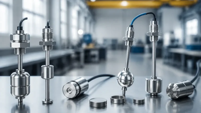
1. Magnetic Reed Switches: This is the most common design for industrial vertical float switches. A permanent magnet is sealed inside the float. As the float slides up or down a stationary stem, the magnet passes over a hermetically sealed reed switch located inside the stem. The magnetic field causes the reed switch contacts to close (or open), completing an electrical circuit.
2. Mechanical Microswitches: Often found in side-mounted or heavy-duty cable float switches, the movement of the float moves a lever or a ball-bearing mechanism that physically presses a microswitch button. These are robust and can often handle higher electrical currents than reed switches.
3. Mercury Switches (Legacy): While largely phased out due to environmental regulations, some older systems used a tilting glass bulb containing mercury. When the float tilted, the mercury flowed to one end, connecting two electrodes. Modern equivalents use eco-friendly rolling-ball mechanisms to achieve the same effect.
High and Low Level Logic
High and low level float switches are categorized by their intended function within a tank or vessel. While the hardware may be similar, the configuration and placement differ significantly.
High Level Detection (High Alarm/Overflow Prevention)
High level switches are positioned near the top of a vessel. Their primary roles include:
* Overfill Prevention: Automatically shutting off an inlet pump or closing a fill valve before the liquid spills over the tank brim.
* Alarm Notification: Triggering an audible or visual alarm to alert operators that the tank is reaching maximum capacity.
* Redundancy: Acting as a secondary safety layer (LSHH – Level Switch High High) in case the primary continuous level transmitter fails.
Low Level Detection (Low Alarm/Dry-Run Protection)
Low level switches are positioned near the bottom of a vessel. Their primary roles include:
* Pump Protection: Preventing a pump from running dry, which can lead to cavitation, seal damage, and motor burnout.
* Process Continuity: Triggering an automatic refill cycle to ensure that downstream processes always have an adequate supply of liquid.
* Heater Protection: In tanks with immersion heaters, a low-level switch ensures the heating elements remain submerged to prevent overheating and fire risks.
Types of High and Low Level Float Switches
1. Vertical Float Switches
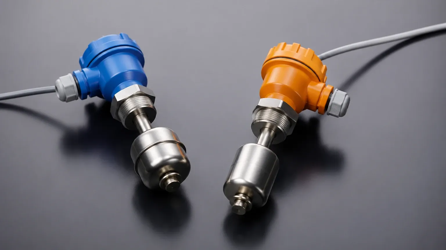
These are mounted through the top or bottom of a tank. They consist of a stem and one or more floats. Multi-point vertical switches can incorporate both a high-level and a low-level sensor on a single stem, reducing the number of tank penetrations required.
2. Side-Mounted (Horizontal) Float Switches
These are installed through the side wall of a tank. When the liquid reaches the level of the switch, the float hinges upward or downward to actuate the internal mechanism. These are ideal for tanks where there is no access to the top or where the top is occupied by other equipment.
3. Cable-Suspended Float Switches
Commonly used in wastewater sumps and large reservoirs, these switches consist of a weighted float attached to a flexible cable. The switch triggers when the float tilts beyond a certain angle. They are highly durable and resistant to fouling from solids.
Practical Selection Criteria
Choosing the right high and low level float switches involves evaluating several technical parameters to ensure long-term reliability.
Material Compatibility
The material of the float and stem must be chemically compatible with the process liquid.
* Stainless Steel (316L): The standard for food processing, pharmaceuticals, and high-pressure oil and gas applications. It resists corrosion and can withstand temperatures up to 200°C (392°F).
* Polypropylene (PP): A cost-effective choice for water treatment and many acidic or alkaline chemicals. It is lightweight but limited to lower temperatures, typically up to 80°C (176°F).
* PVDF/PTFE: Used for highly aggressive chemical environments where even stainless steel might fail.
Specific Gravity
The float must be lighter than the liquid it is intended to measure. Most standard floats are designed for liquids with a specific gravity (SG) of 0.80 or higher (water is 1.0). If you are measuring light oils or hydrocarbons with an SG of 0.65, a specialized, high-buoyancy float is required.
Pressure and Temperature
Standard plastic switches are often limited to atmospheric pressure. For pressurized vessels (e.g., boilers or chemical reactors), stainless steel floats capable of withstanding 30 bar (435 PSI) or higher are necessary. Always verify that the operating temperature does not exceed the switch's rating, as heat can demagnetize internal components or degrade seals.
Electrical Configuration
* Normally Open (N.O.) vs. Normally Closed (N.C.): Many float switches are reversible. By removing a retaining clip and flipping the float 180 degrees, the switch logic can be changed from N.O. to N.C.
* Contact Rating: Reed switches often have low current ratings (e.g., 0.5A). If you need to drive a large motor directly, you must use a relay or contactor to protect the switch from inductive surges.
Comparison Table: Float Switch Technologies
| Feature | Vertical Reed Switch | Side-Mounted Switch | Cable Float Switch |
| :— | :— | :— | :— |
| Mounting Position | Top or Bottom | Side Wall | Suspended from Top |
| Accuracy/Repeatability | High (±2mm) | Moderate (±5mm) | Low (±20mm+) |
| Max Temperature | Up to 200°C (SS) | Up to 150°C | Up to 70°C |
| Solids Tolerance | Low (can jam) | Moderate | High (excellent) |
| Multi-Point Support | Yes (up to 7 points) | No (single point) | No (single point) |
| Typical Application | Chemical tanks, fuel | Small reservoirs, OEM | Sewage, sumps, wells |
Installation Considerations and Best Practices
To ensure the longevity of high and low level float switches, follow these engineering guidelines during installation:
1. Avoid Turbulence: Do not install a float switch directly in the path of an inlet pipe. The turbulent flow can cause the float to bounce, leading to "chatter" (rapid cycling of the switch), which can damage pumps and burn out contacts. Use a stilling well (a perforated pipe) if turbulence is unavoidable.
2. Maintain Clearance: Ensure the float has enough clearance from the tank walls and internal structures like ladders or agitators. For vertical switches, ensure the stem is perfectly plumb.
3. Wiring Protection: Use waterproof conduits and cable glands. In outdoor or humid environments, moisture can wick through the cable and corrode the internal switch contacts.
4. Inductive Load Protection: If the switch is controlling a solenoid valve or a relay coil, install a diode (for DC) or an RC snubber (for AC) across the load to suppress voltage spikes.
Limitations and Risks
While highly effective, float switches are not suitable for every application. Engineers should be aware of the following risks:
* Coating and Scaling: In liquids that crystallize or contain heavy oils, material can build up on the stem or float. This increases the weight of the float or causes it to stick, leading to a failure to trigger.
* Magnetic Interference: In environments with high concentrations of ferrous metal particles (e.g., machining coolant tanks), metal fines can be attracted to the float's internal magnet, eventually jamming the mechanism.
* Mechanical Wear: Because they have moving parts, float switches will eventually wear out. In high-cycle applications, non-contact technologies like ultrasonic or radar may be more appropriate.
Frequently Asked Questions (FAQ)
Q: Can I use a single float switch for both high and low level control?
A: A single-point float switch can only detect one level. However, you can use a vertical stem with two separate floats and two internal reed switches to monitor both high and low levels through a single tank opening.
Q: How do I test a float switch without filling the tank?
A: For most vertical and side-mounted switches, you can manually move the float with your hand to verify the electrical continuity. For cable switches, simply tilt the float body to the trigger angle.
Q: What is the difference between a float switch and a float level transmitter?
A: A float switch provides a discrete "on/off" signal at a specific point. A float level transmitter (often using a magnetostrictive or resistive chain) provides a continuous signal (e.g., 4-20mA) representing the exact level across the entire range of the stem.
Q: Are float switches safe for explosive environments?
A: Yes, but you must use an intrinsically safe (IS) barrier or an explosion-proof housing. Since the reed switch itself is a "simple apparatus," it can be used in hazardous areas when connected to a properly rated IS controller.
Conclusion
High and low level float switches remain a cornerstone of industrial level control due to their simplicity and reliability. By understanding the chemical and physical demands of the application—ranging from specific gravity to pressure ratings—engineers can implement robust solutions that protect equipment and optimize processes. For complex installations or specialized chemical requirements, consulting with a manufacturer of professional Level Switches is recommended to ensure the selected device meets all safety and performance benchmarks.