Level 0 Switch
Level 0 Switch
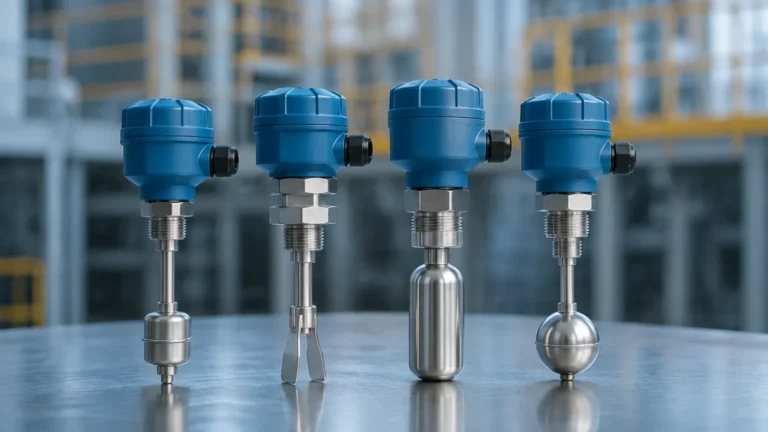
In the architecture of industrial automation, the term "Level 0" refers to the physical process layer—the actual field environment where sensors and actuators interact with the media. A level 0 switch is a fundamental component within this layer, responsible for providing discrete, binary feedback regarding the presence or absence of a substance at a specific point. These devices, more broadly known as Level Switches, serve as the first line of defense in overfill protection, pump control, and dry-run prevention.
Understanding the mechanics of these field-level devices is essential for process engineers and system integrators. Unlike continuous level transmitters that provide a 4-20mA or digital signal representing the entire range of a tank, a level 0 switch triggers a state change (typically an open or closed contact) when the material reaches a predetermined height. This article explores the technical principles, selection criteria, and installation requirements for these critical field instruments.
Core Measurement Principles of Level 0 Switches
Before selecting a specific technology, it is necessary to understand how different physical principles are leveraged to detect level. The choice of principle depends heavily on the physical properties of the media, such as density, conductivity, and viscosity.
1. Vibrating Fork (Tuning Fork) Principle
This technology utilizes a fork-shaped sensing element that is vibrated at its natural resonant frequency by a piezoelectric crystal. When the fork is immersed in a liquid or solid, the frequency changes or the vibration is dampened. The internal electronics detect this shift and switch the output state. Vibrating forks are highly versatile because they are largely unaffected by flow, turbulence, bubbles, or foam.
2. Float and Magnetic Principle
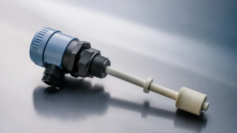
Float-based level 0 switches operate on the principle of buoyancy. A float containing a permanent magnet moves with the liquid level. When the float reaches a specific point, the magnetic field actuates a hermetically sealed reed switch located within the stationary stem. This method is purely mechanical/magnetic and does not require power to the sensing element itself, making it a reliable choice for basic liquid applications.
3. Capacitive and RF Admittance Principle
A capacitive sensor acts as one plate of a capacitor, while the tank wall (or a reference probe) acts as the second plate. The media serves as the dielectric. As the level rises and covers the probe, the capacitance increases due to the higher dielectric constant of the material compared to air. RF Admittance is an advanced version of this principle that uses a driven shield to ignore the effects of material build-up on the probe, which is a common failure point for standard capacitive switches.
4. Ultrasonic Gap Principle
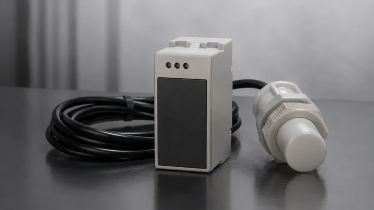
These switches consist of two ultrasonic transducers separated by a small gap. One transducer emits an ultrasonic signal, and the other receives it. When the gap is filled with air, the signal is too weak to reach the receiver. When liquid fills the gap, the ultrasonic energy is transmitted efficiently, triggering the switch. This is ideal for clean liquids and is often used in high-level alarm systems.
Selection Criteria for Level 0 Field Devices
Selecting a level 0 switch requires an evaluation of the operational environment. A mismatch between the technology and the application can lead to false alarms or, more dangerously, a failure to trigger during an overfill event.
Media Characteristics
* Density (Specific Gravity): Float switches require a minimum media density to provide enough buoyant force to move the float. Tuning forks also have minimum density requirements (typically >0.5 g/cm³ or 31.2 lb/ft³) to ensure the vibration is sufficiently dampened.
* Viscosity: High-viscosity liquids can cause "clinging" on tuning forks or capacitive probes, leading to delayed switching or false positives. In these cases, RF Admittance or heavy-duty mechanical floats are preferred.
* Conductivity: Conductivity switches require the liquid to be electrically conductive. If the media is non-conductive (like pure oils or deionized water), this technology will not function.
Process Conditions
* Pressure and Temperature: Field-level devices must withstand the internal pressure of the vessel. Standard switches may handle up to 40 bar (580 psi), but high-pressure variants are available for steam or hydraulic applications. Temperature ratings must account for both the process media and the ambient environment near the electronics.
* Chemical Compatibility: The "wetted parts" (the components in contact with the media) must be resistant to corrosion. Common materials include 316L Stainless Steel, Hastelloy, or plastics like PP and PVDF for corrosive acids.
Engineering Installation Considerations
The physical placement of a level 0 switch is as important as the technology itself. Improper installation is the leading cause of premature sensor failure.
Orientation and Positioning
Switches can be installed horizontally (through the side of the tank) or vertically (from the top).
* Side Mounting: Ideal for point-level detection at specific heights. Ensure the nozzle length does not exceed the manufacturer's recommendations; if the nozzle is too long, material can become trapped, preventing the sensor from resetting.
* Top Mounting: Preferred for low-level detection or when side access is restricted. Vertical probes may require support if they exceed 2 meters (6.5 feet) in length to prevent bending from fluid movement.
Turbulence and Agitation
In tanks with agitators or high-velocity inflow, the physical force of the liquid can damage delicate probes. Installation should be away from the direct path of the inflow. If turbulence is unavoidable, a stilling well (a perforated pipe surrounding the sensor) should be used to provide a calm environment for the measurement.
Wiring and Signal Integration
At Level 0, the electrical output is usually a relay contact (SPDT/DPDT), a transistor output (PNP/NPN), or a two-wire contact. It is critical to ensure the voltage and current ratings of the switch match the input requirements of the Level 1 controller (PLC or DCS). For hazardous areas, intrinsically safe barriers or explosion-proof housings are mandatory to prevent ignition sources in the field.

Practical Selection Table
The following table provides a general guideline for choosing a level 0 switch based on common industrial media types.
| Media Type | Recommended Technology | Primary Advantage | Limitation |
| :— | :— | :— | :— |
| Clean Water | Float Switch | Low cost, simple | Moving parts can wear |
| Corrosive Acids | Plastic Capacitive | Chemical resistance | Sensitive to coating |
| Viscous Oils | Vibrating Fork | High reliability | May require "heavy" fork calibration |
| Dry Powders | Rotating Paddle | Robust for solids | Mechanical motor wear |
| Non-conductive Liquids | Ultrasonic Gap | No moving parts | Not for aerated liquids |
| Wastewater/Sludge | RF Admittance | Ignores build-up | Higher initial cost |
Limitations and Common Risks
While level 0 switches are designed for reliability, they are not infallible. Engineers must account for the following risks during the design phase:
1. Material Coating: In applications involving sticky or crystallizing media, material can build up on the sensing element. This creates a "bridge" that mimics the presence of the media even when the level has dropped. Selecting a switch with "coating rejection" capabilities is vital for these processes.
2. Mechanical Fatigue: For switches with moving parts, such as float switches or rotating paddles, mechanical wear is inevitable. These devices require periodic inspection to ensure the float has not been punctured and the seals remain intact.
3. False Triggers from Foam: Some technologies, particularly ultrasonic and certain capacitive sensors, may struggle to distinguish between the actual liquid level and a thick layer of foam. Tuning forks are generally the most resilient to foam interference.
4. Environmental Noise: In RF or capacitive systems, electromagnetic interference (EMI) from nearby high-voltage motors can induce noise into the signal. Proper shielding and grounding are required to maintain signal integrity at the field level.
Frequently Asked Questions (FAQ)
Q: Can a level 0 switch be used for continuous level measurement?
A: No. A level 0 switch only provides a "yes/no" signal at a specific point. For continuous tracking (e.g., 0% to 100% volume), a radar, ultrasonic, or hydrostatic level transmitter is required.
Q: What is the difference between a "Normally Open" (NO) and "Normally Closed" (NC) configuration?
A: This refers to the state of the switch when it is not activated by the media. For fail-safe overfill protection, a "Normally Closed" contact is often used so that if power is lost or a wire is cut, the system interprets it as a high-level alarm.
Q: How do I handle a level 0 switch in a pressurized vessel?
A: You must select a switch with a process connection (flange or thread) and a body rating that exceeds the maximum possible vessel pressure. Always check the pressure-temperature curve provided by the manufacturer, as the pressure rating often drops as temperature increases.
Q: Is maintenance required for solid-state level switches?
A: While solid-state switches like tuning forks have no moving parts, they should still be inspected for corrosion or significant material build-up that could eventually impede the vibration or sensing field.
For engineers looking to implement robust point-level detection in their automation systems, selecting the correct Level Switches is a matter of matching the physical sensing principle to the specific challenges of the process media. By focusing on the Level 0 requirements—the physical interaction between sensor and substance—operators can ensure long-term accuracy and safety in their industrial applications.