Level Switch 2 Wire
Level Switch 2 Wire
In industrial automation and process control, the electrical interface of a sensing device is as critical as its physical measurement principle. A level switch 2 wire configuration represents a specific design where the device uses only two conductors to both receive power and transmit its switching signal. This setup is highly valued in large-scale industrial plants for its ability to reduce cabling costs, simplify installation, and integrate seamlessly with programmable logic controllers (PLCs) and distributed control systems (DCS).
Understanding the nuances of 2-wire technology is essential for instrumentation engineers. Unlike traditional 3-wire or 4-wire switches, which have dedicated power supply lines and separate output contacts, a 2-wire switch operates in series with the load. This article explores the measurement principles, selection criteria, and technical limitations of 2-wire Level Switches to assist in effective system design.
Measurement Principles for 2-Wire Level Switches
While "2-wire" refers to the electrical output, the internal sensing technology can vary significantly. Most modern electronic level switches are designed to support 2-wire loops by utilizing low-power circuitry. The following are the most common measurement principles employed in these configurations.
1. Vibrating Fork (Tuning Fork)
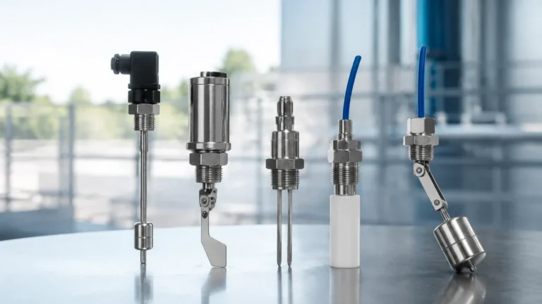
This is perhaps the most common technology for a level switch 2 wire setup. A piezoelectric crystal vibrates a metal fork at its natural frequency (typically around 1,200 Hz to 1,400 Hz). When the fork is submerged in a liquid, the frequency shifts or the amplitude drops. The internal electronics detect this change and alter the current consumption of the device to signal a state change. Because the piezoelectric drive requires very little power, it is ideal for 2-wire loops.
2. Capacitance Level Sensing
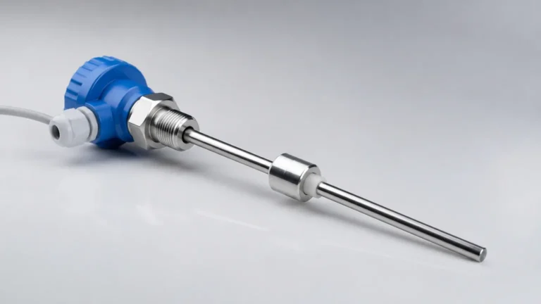
Capacitance switches measure the dielectric constant of the medium between the probe and the tank wall. As the liquid level rises and covers the probe, the capacitance increases. In a 2-wire configuration, the sensor converts this capacitance change into a discrete switching signal. These are often used for detecting powders, granules, or non-conductive liquids.
3. Ultrasonic Gap Switches
These sensors utilize two ultrasonic transducers separated by a small gap. When the gap is filled with liquid, ultrasonic waves travel from the transmitter to the receiver. In air, the signal is attenuated. The electronics then toggle the output. Like the vibrating fork, the low power consumption of ultrasonic crystals allows for efficient 2-wire operation.
4. Conductive Level Switches
These are the simplest forms of 2-wire switches, used specifically for conductive liquids. The liquid completes a circuit between two electrodes or an electrode and the tank wall. While fundamentally 2-wire in nature, they often require an external controller to provide the low-voltage AC signal needed to prevent electrolysis.
The Technical Mechanics of 2-Wire Operation
A 2-wire switch operates on the principle of "current modulation" or "series load switching." It is important to distinguish between the two primary types of 2-wire electrical outputs:
* Contactless Electronic Switch (AC/DC): The switch acts like a solid-state relay in series with the load. In the "OFF" state, a small leakage current flows to power the sensor. In the "ON" state, the switch allows current to flow to the load, but retains a small voltage drop across itself to maintain internal power.
* NAMUR Signal (DIN 19234): This is a specific type of 2-wire interface used primarily in hazardous areas. The switch changes its internal resistance, causing the current in the loop to switch between two levels (typically <1.2 mA for "OFF" and >2.1 mA for "ON"). This requires a compatible NAMUR isolation amplifier.
Comparison Table: 2-Wire vs. 3-Wire Configurations
| Feature | 2-Wire (Series Load) | 3-Wire (PNP/NPN) |
| :— | :— | :— |
| Wiring Complexity | Low (2 leads) | Moderate (3 leads) |
| Power Source | From the load loop | Dedicated V+ and V- |
| Leakage Current | Present (0.5 mA to 1.5 mA) | Negligible |
| Voltage Drop | Significant (typically 5V – 8V) | Minimal (<1V) |
| Installation Cost | Lower (less cable/labor) | Higher |
| Compatibility | Requires specific PLC input impedance | Universal for most PLCs |
Practical Selection Table for 2-Wire Level Switches
When selecting a level switch 2 wire for a specific application, engineers must balance the media properties with the electrical requirements of the control system.
| Technology | Best Suited Media | Max Pressure | Temp Range | Key Advantage |
| :— | :— | :— | :— | :— |
| Vibrating Fork | Water, Oils, Chemicals | 40 bar (4.0 MPa) | -40°C to 150°C | High reliability, no calibration |
| Capacitance | Solids, Non-conductive liquids | 25 bar (2.5 MPa) | -40°C to 200°C | No moving parts, handles coatings |
| Ultrasonic Gap | Clean liquids, Aerated liquids | 20 bar (2.0 MPa) | -30°C to 100°C | Unaffected by dielectric changes |
| Magnetic Float | Clean, low-viscosity liquids | 30 bar (3.0 MPa) | -20°C to 120°C | Simple, no power required (Passive) |
Installation and Wiring Considerations
Proper installation of a level switch 2 wire is vital to prevent "ghosting" signals or device failure. Because these devices are wired in series with the load (such as a PLC input or a relay coil), the electrical characteristics of that load must be matched.
1. Minimum Load Requirement
Electronic 2-wire switches require a minimum current to operate. If the load (e.g., a high-impedance PLC input) does not draw enough current, the switch may not power up correctly. In such cases, a shunt resistor may be required across the input terminals to increase the current flow.
2. Residual (Leakage) Current
In the "OFF" state, the switch still passes a small amount of current (leakage current) to keep its internal sensors active. If this leakage current is too high, the PLC may interpret it as an "ON" signal. Engineers should verify that the PLC's maximum "OFF" state current threshold is higher than the switch's leakage current (typically <1.5 mA).
3. Voltage Drop
When the switch is "ON," it consumes a portion of the supply voltage (voltage drop). For a 24V DC system, if the switch has a 7V drop, only 17V will reach the load. It is critical to ensure that the remaining voltage is sufficient to trigger the PLC input or energize the relay coil.
4. Cable Length and Interference
Since 2-wire loops often carry low-level signals, they can be susceptible to electromagnetic interference (EMI). Using shielded twisted-pair cables (e.g., 0.75 mm² or 18 AWG) is recommended, especially for long runs exceeding 100 meters.
Limitations and Risks
While the level switch 2 wire offers simplicity, it is not suitable for every application. Engineers should be aware of the following limitations:
* Coating and Buildup: For capacitance-based 2-wire switches, significant material buildup on the probe can lead to false triggers. While some models feature "active shield" technology to ignore buildup, this often increases the power requirement, sometimes pushing the device out of the standard 2-wire power budget.
* High-Speed Switching: 2-wire electronic switches often have a slight delay (typically 500ms to 1s) upon power-up or state change as the internal capacitors charge or discharge. This makes them unsuitable for high-speed counting or extremely rapid level fluctuations.
* Polarity Sensitivity: Most DC 2-wire switches are polarity sensitive. Reversing the wires will prevent the device from functioning, though most modern Welk units include reverse polarity protection to prevent damage.
Frequently Asked Questions (FAQs)
Q: Can I connect a 2-wire level switch directly to a motor?
A: Generally, no. A 2-wire electronic level switch is designed for signal-level currents (typically <100 mA). Connecting it directly to a motor will exceed its current rating and destroy the output stage. You must use the switch to trigger a contactor or an interposing relay.
Q: What is the difference between a 2-wire switch and a 4-20mA transmitter?
A: A 2-wire switch provides a discrete (On/Off) signal by changing its current state. A 4-20mA transmitter provides a continuous (analog) signal proportional to the level. While both use two wires, the switch is for point detection, and the transmitter is for continuous measurement.
Q: How do I test a 2-wire switch with a multimeter?
A: You cannot easily test an electronic 2-wire switch using the "continuity" setting on a multimeter because it requires a power source to operate. To test it, you must apply the rated voltage in series with a suitable load and measure the voltage drop or current change across the circuit.
Q: Are 2-wire switches safe for hazardous areas?
A: Yes, many 2-wire switches are designed for Intrinsic Safety (IS). When used with a Zener barrier or a galvanic isolator, they limit the energy entering the hazardous area, making them suitable for Zone 0, 1, or 2 applications.
Conclusion
The level switch 2 wire remains a preferred choice for industrial level detection due to its efficiency and reduced infrastructure requirements. By understanding the relationship between the sensing technology and the electrical loop requirements, facilities can ensure reliable overfill protection and pump control. For complex applications involving aggressive chemicals or high-pressure environments, consulting with a manufacturer to match the switch impedance with the control system is a recommended best practice. For more information on various configurations and housing options, you can explore the full range of Level Switches available for industrial use.