Level Switch 2
Level Switch 2
In industrial process control, the term "level switch 2" typically refers to the implementation of a second detection point or a secondary redundant switch within a vessel or tank. Whether used for pump control (start/stop) or as a critical safety backup (High-High alarm), the selection and integration of these devices are fundamental to preventing dry-run damage, overflows, and environmental hazards. This guide examines the technical principles, selection criteria, and installation best practices for Level Switches configured for dual-point or redundant applications.
Understanding the Role of Dual-Point Level Switches
A single point of detection is often insufficient for automated processes. A "level switch 2" configuration—where two distinct setpoints are monitored—allows for sophisticated control logic. In a standard filling operation, the first switch might signal the pump to stop at a "High" level, while the second switch acts as a "High-High" emergency shutdown.
In B2B industrial environments, these configurations are categorized into two types:
1. Integrated Multi-Point Switches: A single probe or stem containing two or more independent switching elements (e.g., a magnetic float switch with two internal reed switches).
2. Redundant Discrete Switches: Two entirely separate instruments installed at different heights or in parallel to provide hardware redundancy, often required for Safety Integrity Level (SIL) rated systems.
Measurement Principles for Multi-Point Detection
Before selecting a level switch 2 setup, it is essential to understand the underlying measurement principles. Different technologies react uniquely to fluid properties such as viscosity, dielectric constant, and turbulence.
Magnetic Float Principle
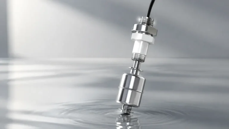
This is the most common technology for dual-point detection in clean liquids. A float containing a permanent magnet moves along a stem. Inside the stem, reed switches are positioned at specific intervals (Level 1 and Level 2). As the float passes these points, the magnetic field opens or closes the circuit. This method is highly reliable for water, oils, and chemicals that do not exhibit high scaling or crystallization.
Vibrating Tuning Fork Principle
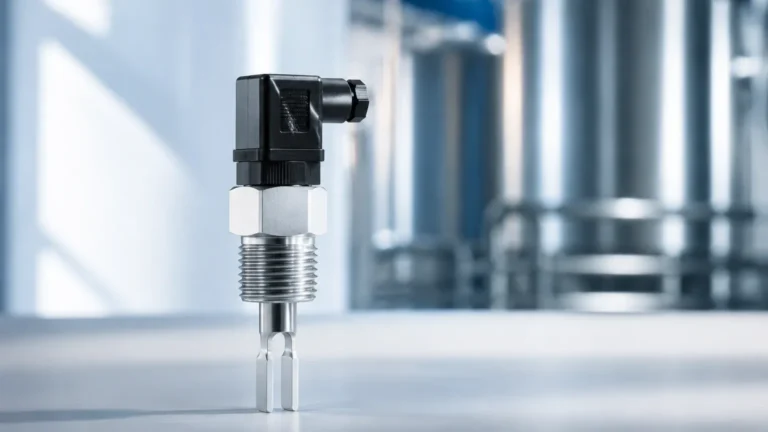
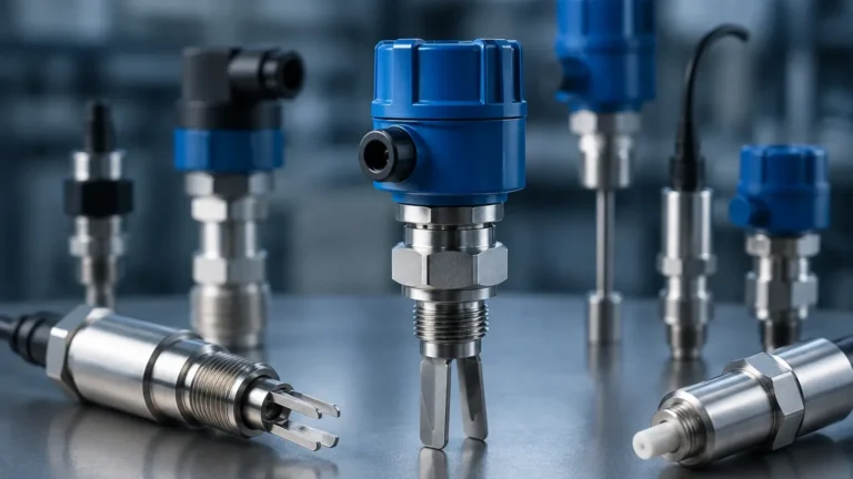
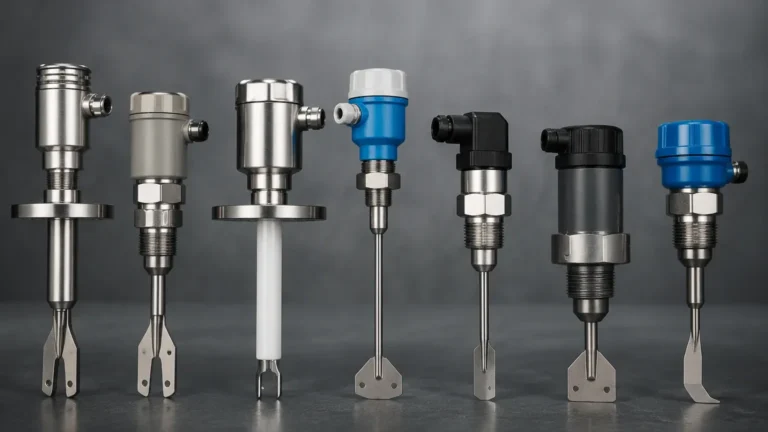
For applications involving powders, granulates, or liquids with varying densities, vibrating level switches are preferred. The fork vibrates at its natural frequency in the air. When the medium covers the fork, the frequency shifts, triggering the switch. Using a level switch 2 configuration with tuning forks usually involves installing two separate units at the desired heights. This technology is immune to bubbles, foam, and external vibrations.
Capacitive Principle
Capacitive switches detect changes in the electrical capacitance between the probe and the tank wall (or a reference electrode). They are particularly effective for detecting the interface between two different liquids or for monitoring sticky substances. A dual-point capacitive system can be calibrated to ignore slight coating on the probe while still providing an accurate trigger at the second setpoint.
Ultrasonic Gap Principle
These switches utilize a pair of ultrasonic crystals separated by a small gap. When the gap is filled with liquid, the ultrasonic signal is transmitted; when empty, the signal is attenuated. This is an excellent choice for highly aerated liquids or when a non-mechanical, solid-state solution is required for high-reliability "Level 2" safety loops.
Key Evaluation Criteria for Secondary Level Switches
When specifying a level switch 2 for a project, engineers must look beyond the basic measurement type. The following criteria determine the long-term viability of the instrument in a B2B industrial context:
* Hysteresis and Repeatability: Hysteresis is the difference between the switch-on and switch-off points. For a level switch 2 used in pump control, a defined hysteresis prevents "chattering" (rapid cycling of the pump) when the liquid surface is turbulent.
* Wetted Materials: The probe and seals must be compatible with the process media. Common materials include 316L Stainless Steel, PTFE (Teflon), and PP (Polypropylene). In aggressive chemical environments, specialized coatings are necessary to prevent corrosion of the second switch.
* Output Logic (NO/NC): Most industrial switches allow for field-reversible logic. For safety-critical "Level 2" applications, a "Normally Closed" (NC) configuration is typically used so that a power failure or wire break triggers a fail-safe alarm.
* Pressure and Temperature Ratings: Standard switches may operate up to 20 bar (290 psi) and 100°C (212°F), but high-pressure boilers or cryogenic tanks require specialized housings and thermal separators.
Practical Technology Selection Table
The following table provides a comparison of common technologies used in level switch 2 configurations to assist in the engineering selection process.
| Technology | Best Suited For | Limitations | Maintenance Requirement |
| :— | :— | :— | :— |
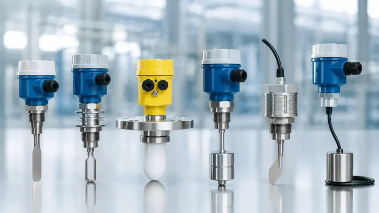
| Magnetic Float | Clean liquids, water, fuel | Susceptible to sticking in dirty fluids | Low to Medium |
| Vibrating Fork | Powders, liquids with foam | Not for extremely high-viscosity pastes | Very Low |
| Capacitive | Slurries, interface detection | Requires calibration for different media | Medium |
| Ultrasonic Gap | Aerated liquids, chemicals | Not for high-solids content | Low |
| Hydrostatic Switch | Deep tanks, wastewater | Sensitive to density changes | Medium |
Installation Guidelines for Redundant Systems
Correct installation is critical to ensure that a level switch 2 functions as intended, especially when it serves as a safety backup.
Positioning and Orientation
* Top-Mounting: Multi-point float switches are typically top-mounted. Ensure the stem is perfectly vertical to prevent the float from binding.
* Side-Mounting: For discrete redundant switches, side-mounting is common. The "Level 2" switch should be placed far enough above the "Level 1" switch to account for surface agitation and the response time of the control system.
* Avoid Turbulence: Do not install switches directly under a fill pipe. The force of the incoming liquid can cause false triggers or mechanical damage to the probe.
Wiring and Integration
In a level switch 2 setup, the wiring should ideally be run through separate conduits if the second switch is a safety-critical backup. This prevents a single cable fault from disabling both the primary control and the emergency alarm. Use shielded cables to protect against electromagnetic interference (EMI) from nearby high-voltage pump motors.
Dead Zone Considerations
The "dead zone" or "unmeasurable zone" at the very top or bottom of a probe must be factored into the tank design. Ensure the level switch 2 setpoint does not fall within this zone, as the instrument will fail to trigger even if submerged.
Common Risks and Limitations
While implementing a level switch 2 increases system reliability, there are inherent risks that must be managed:
1. Media Buildup: In wastewater or food processing, material can accumulate on the switch (bridging). This is a common cause of "stuck" alarms. Vibrating forks or capacitive switches with active shield technology are better suited for these environments than mechanical floats.
2. Specific Gravity Changes: Float-based switches rely on buoyancy. If the process liquid's specific gravity changes significantly (e.g., switching from oil to a water-based solvent), the float may no longer trigger the reed switch at the correct height.
3. Mechanical Fatigue: In high-vibration environments, the internal components of mechanical switches can fail over time. In such cases, solid-state switches (ultrasonic or capacitive) are a more robust choice for the secondary level switch 2.
Frequently Asked Questions (FAQs)
Q: Can I use a single probe for two different liquids?
A: Yes, if you use a capacitive level switch or a multi-float magnetic switch designed for interface detection. This allows you to monitor the level of the bottom liquid (e.g., water) and the top liquid (e.g., oil) simultaneously.
Q: What is the difference between SPDT and DPDT in a level switch?
A: SPDT (Single Pole Double Throw) provides one set of contacts to switch one circuit. DPDT (Double Pole Double Throw) provides two independent sets of contacts, allowing a single level switch 2 to trigger a local alarm and a remote PLC input simultaneously.
Q: How often should a redundant level switch 2 be tested?
A: In safety-critical applications, a "proof test" should be conducted at least annually. This involves manually raising the liquid level or removing the switch to simulate a high-level condition to ensure the entire logic loop remains functional.
Q: Is it better to have two separate switches or one dual-point switch?
A: For control (e.g., pump start/stop), a single dual-point switch is more cost-effective and easier to install. For safety (e.g., overfill prevention), two separate switches are recommended to ensure true hardware redundancy.
By carefully selecting the appropriate technology and adhering to rigorous installation standards, engineers can ensure that their level switch 2 configuration provides accurate, repeatable, and safe level detection for any industrial application. For more detailed specifications on various sensor types, you can explore the full range of Level Switches available for professional process control.