Level Switch High and Low
Level Switch High and Low
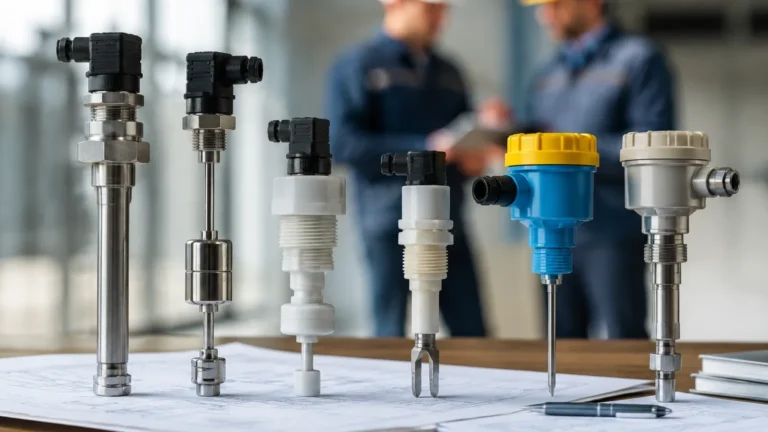
In industrial process control, maintaining the correct volume of liquid or bulk solids within a vessel is fundamental to operational safety and efficiency. A level switch high and low configuration serves as the primary line of defense against vessel overfills and pump dry-running. These point-level detection devices are engineered to trigger an electrical signal when the material reaches a specific height, enabling automated responses such as starting or stopping pumps, opening valves, or activating emergency alarms.
Selecting the appropriate Level Switches requires a deep understanding of the physical properties of the media, the environmental conditions of the process, and the specific logic required for the application. This guide examines the technical principles, selection criteria, and installation best practices for high and low level switching.
Measurement Principles of Level Switches
Before implementing a high/low control strategy, it is essential to understand the underlying technologies. Different sensing principles offer varying degrees of reliability depending on the media's viscosity, conductivity, and dielectric constant.
Float and Displacement Switches
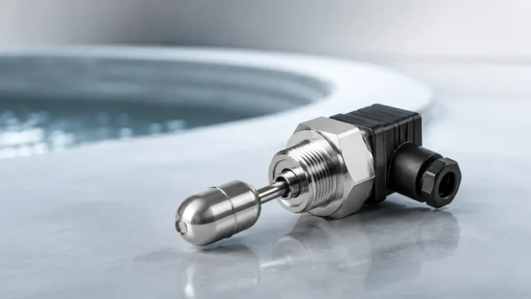
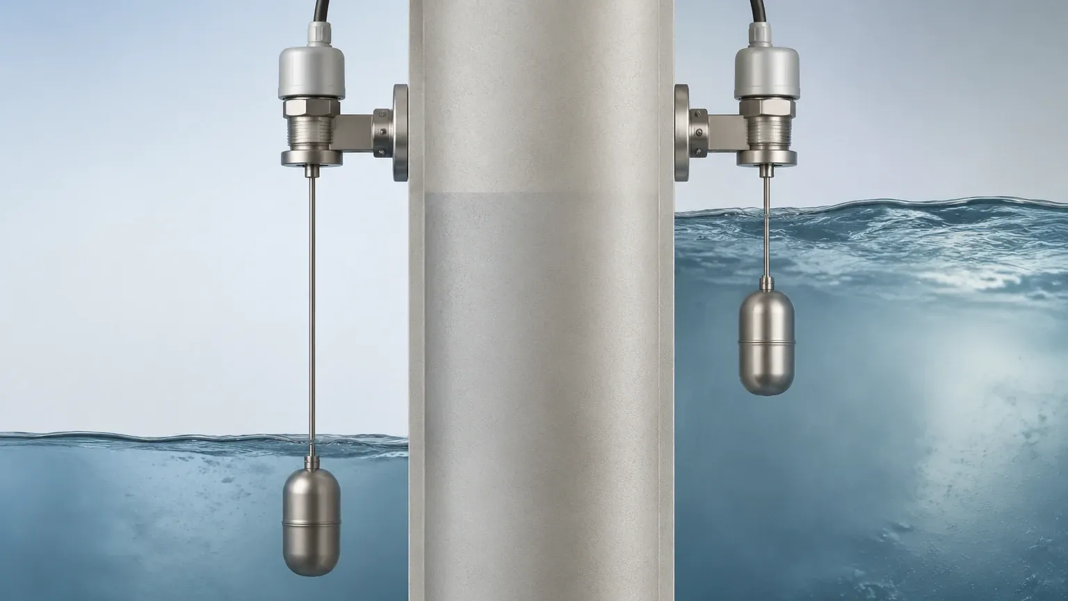
Float switches operate on the principle of buoyancy. A float, containing a magnet, moves with the liquid level. When the float reaches a predetermined point, the magnetic field actuates a reed switch or a microswitch.
* Application: Best for clean liquids with stable densities.
* Limitations: Susceptible to mechanical jamming if the liquid contains debris or high viscosity.
Vibrating Level Switches (Tuning Fork)
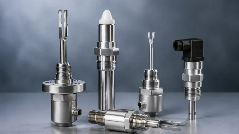
Vibrating switches use a tuning fork sensor that is energized piezoelectrically to vibrate at its natural frequency in air. When the fork is submerged in the medium, the frequency changes or the vibration is damped. This change is detected by the electronics and converted into a switching signal.
* Application: Highly versatile; suitable for liquids, powders, and granulates. They are largely unaffected by flow, turbulence, bubbles, or foam.
* Limitations: Not ideal for extremely sticky media that can bridge the forks.
Capacitance Level Switches
These sensors measure the change in electrical capacitance between the probe and the tank wall (or a reference electrode). As the material rises and covers the probe, the dielectric constant changes, altering the capacitance value.
* Application: Excellent for aggressive chemicals and high-temperature environments.
* Limitations: Requires calibration and can be sensitive to material buildup on the probe unless "active shield" technology is used.
Ultrasonic Level Switches
Ultrasonic switches utilize a pair of crystals (transmitter and receiver) separated by a gap. When liquid fills the gap, ultrasonic waves travel across it; when the gap is empty (filled with air/gas), the signal is attenuated.
* Application: Non-contact or gap-style sensing for highly corrosive or ultrapure liquids.
* Limitations: Performance can be degraded by heavy aeration or high-pressure steam.
The Logic of High and Low Level Switching
A standard level switch high and low setup typically involves at least two detection points. The logic governing these points is designed to maintain the level within a safe "operating window."
High Level (HL) and High-High (HH)
* High Level (HL): This is the normal upper limit. When reached, the switch typically signals the feed pump to stop or the inlet valve to close. It prevents the vessel from reaching a state of overflow during routine operations.
* High-High Level (HH): This is an emergency setpoint located above the HL. If the HL switch fails or the inflow exceeds the outflow capacity, the HH switch triggers an Emergency Shutdown (ESD) or an independent audible alarm. This is a critical safety requirement in chemical and oil and gas sectors.
Low Level (LL) and Low-Low (LL)
* Low Level (LL): This indicates the minimum operational volume. When the level drops to this point, the switch signals the pump to start (to refill the tank) or signals a discharge valve to close.
* Low-Low Level (LL): Located at the bottom of the vessel, this switch protects equipment. For example, it prevents a pump from "dry-running," which can cause catastrophic seal and impeller damage due to lack of lubrication and cooling.
Practical Selection Table for Level Switches
When specifying a level switch high and low system, engineers should refer to the following comparison to match technology with application requirements.
| Technology | Media Type | Temp. Range (Typical) | Pressure Range (Typical) | Key Advantage |
| :— | :— | :— | :— | :— |
| Float | Clean Liquids | -40°C to 200°C (-40°F to 392°F) | Up to 40 bar (580 psi) | Low cost, no power required (passive) |
| Tuning Fork | Liquids/Solids | -50°C to 150°C (-58°F to 302°F) | Up to 64 bar (928 psi) | Maintenance-free, no calibration |
| Capacitance | Liquids/Slurries | -100°C to 400°C (-148°F to 752°F) | Up to 100 bar (1450 psi) | Handles extreme temperatures/pressures |
| Conductivity | Conductive Liquids | -20°C to 100°C (-4°F to 212°F) | Up to 10 bar (145 psi) | Simple, multiple points on one probe |
| Ultrasonic | Non-coating Liquids | -40°C to 135°C (-40°F to 275°F) | Up to 40 bar (580 psi) | No moving parts, reliable in clean fluids |
Installation Considerations and Best Practices
The reliability of a level switch high and low system depends heavily on correct physical installation. Even the most advanced sensor will fail if placed in an unsuitable location.
1. Avoid Turbulence and Inlets: Do not install switches directly under a fill pipe or near an agitator. The splashing and localized turbulence can cause "chattering" (rapid cycling of the relay), leading to premature failure of the switch and the connected equipment.
2. Stilling Wells: If turbulence is unavoidable, install the switch inside a stilling well (a vertical pipe with vent holes) to provide a calm surface for measurement.
3. Orientation:
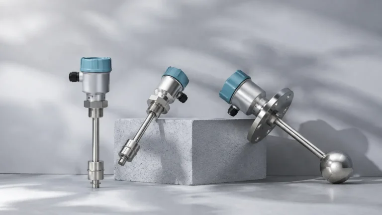
* Side Mounting: Common for high/low alarms. Ensure the probe is angled slightly downward (approx. 20°) if the media is prone to buildup, allowing moisture or particles to shed off.
* Top Mounting: Ideal for low-level detection where the probe must reach deep into the tank. Ensure the rod or cable length is accurately specified.
4. Fail-Safe Modes:
* High-Level Fail-Safe (MAX): The relay is energized when the level is below the switch. If power is lost, the relay de-energizes, indicating a "high" condition. This prevents overflow during power failure.
* Low-Level Fail-Safe (MIN): The relay is energized when the level is above the switch. If power is lost, it signals a "low" condition, protecting pumps from dry-running.
5. Wiring and Grounding: For capacitance and electronic switches, ensure the sensor is properly grounded to the metal tank wall or a dedicated ground rod to maintain signal integrity.
Limitations and Common Risks
While level switches are robust, certain process conditions can compromise their accuracy:
* Material Buildup: In applications involving wastewater or sticky resins, material can coat the sensor. Tuning forks and capacitance probes with "coating rejection" features are preferred here.
* Foam and Bubbles: Some technologies, like ultrasonic or optical switches, may misinterpret thick foam as a solid level or fail to see through it. Vibrating forks are generally the best solution for foamy liquids.
* Specific Gravity Changes: Float switches rely on buoyancy. If the process liquid changes (e.g., switching from oil to water), the float may sit higher or lower in the liquid, shifting the switching point.
* Dielectric Constant (Dk): Capacitance switches require a minimum Dk to function. If the medium has a very low Dk (like certain oils or dry powders), a high-sensitivity probe is required.
Frequently Asked Questions (FAQ)
1. Can one switch handle both high and low levels?
Generally, no. A single-point level switch can only detect the presence or absence of material at one specific height. To manage both high and low levels, you typically need two separate switches or a single multi-point probe (common in conductivity or float-type designs).
2. What is the difference between a level switch and a level transmitter?
A level switch provides a discrete "on/off" signal at a specific point. A level transmitter provides continuous measurement (e.g., 4-20mA or Modbus signal) of the entire range from 0% to 100%.
3. How do I test a level switch high and low system without filling the tank?
Most modern electronic switches (like tuning forks) feature a "test button" or a magnetic test point that simulates a covered state. For mechanical floats, manual lifting of the float (if accessible) is required.
4. What is the standard output for industrial level switches?
The most common outputs are SPDT (Single Pole Double Throw) or DPDT (Double Pole Double Throw) relays, PNP/NPN transistor outputs, or two-wire contactless electronic switches.
5. Why is my level switch chattering?
Chattering is usually caused by surface waves or turbulence. This can be resolved by increasing the "hysteresis" (the difference between the switch-on and switch-off points) in the controller logic or by installing a stilling well.
Conclusion
Implementing a reliable level switch high and low system is a fundamental engineering requirement for process safety. By selecting the right technology—whether it be the simplicity of a float switch or the versatility of a vibrating tuning fork—and adhering to strict installation guidelines, operators can significantly reduce the risk of environmental spills and equipment damage. For complex applications involving high pressures or corrosive media, consulting with a manufacturer to customize the sensor material and mounting is recommended to ensure long-term performance.