Level Switch Horizontal
Level Switch Horizontal
In industrial process control, point-level detection is a critical safety and operational requirement. While vertical installation is common, many applications necessitate a level switch horizontal configuration. This orientation involves mounting the sensor through the side wall of a tank or vessel rather than from the top. Side-mounting is often the preferred choice when overhead space is limited, when the vessel is extremely tall, or when internal obstructions like agitators and spray balls prevent vertical access.
Selecting the correct horizontal level switch requires a deep understanding of the measurement principles, the physical properties of the media, and the specific mechanical constraints of the installation site. This guide provides a technical overview of horizontal level detection technologies, selection criteria, and engineering best practices.
Measurement Principles for Horizontal Installation
Several technologies are adapted for horizontal mounting. Each operates on a distinct physical principle to detect the presence or absence of a liquid at a specific point.
1. Magnetic Float Level Switches
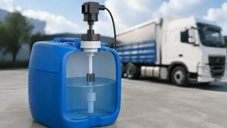
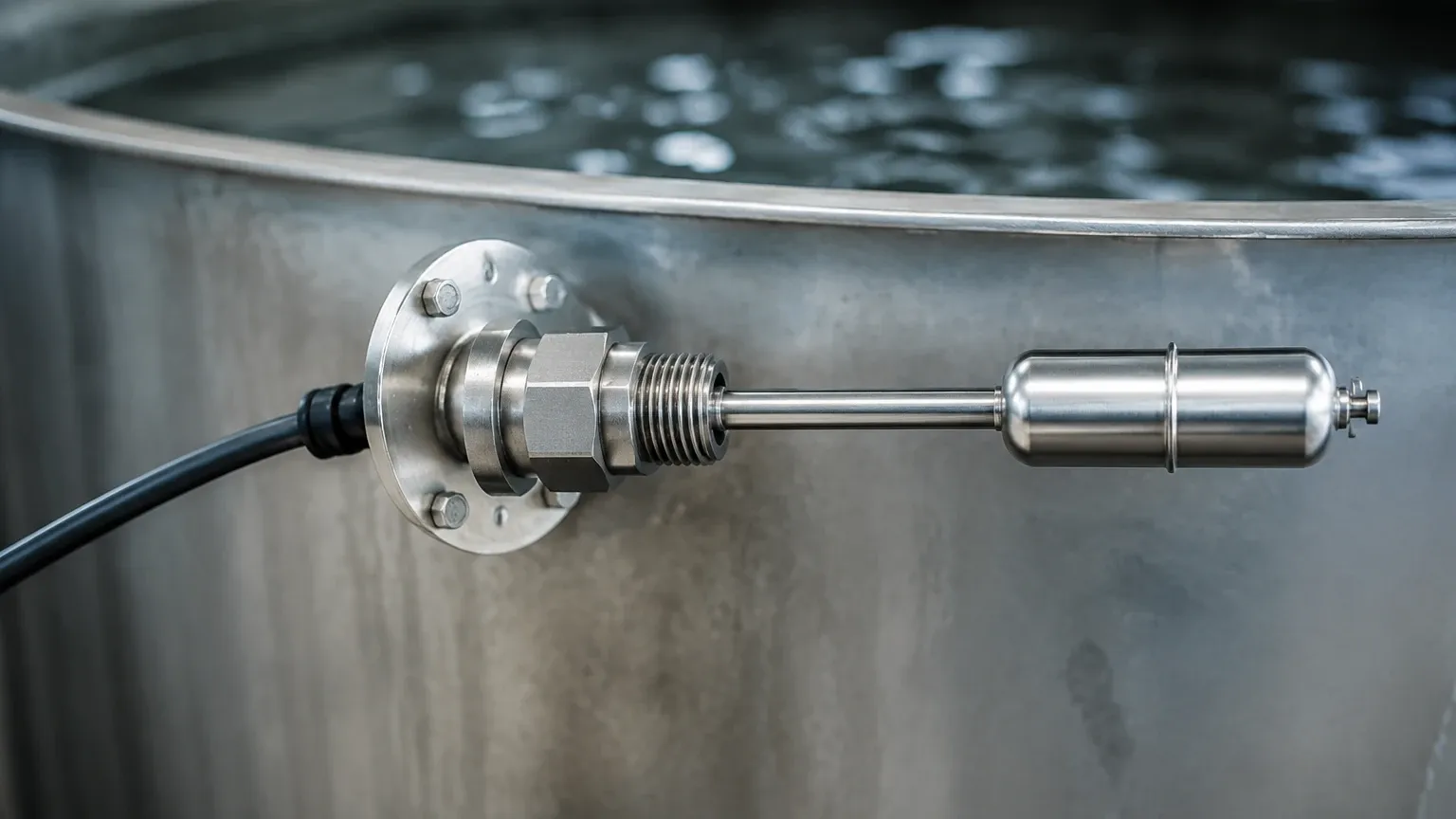
The magnetic float switch is one of the most established technologies for horizontal applications. It consists of a float containing a permanent magnet and a housing containing a reed switch or microswitch.
* Operation: As the liquid level rises to the mounting point, the buoyancy force causes the float to pivot or slide. The internal magnet moves closer to the reed switch, changing its state (normally open to normally closed, or vice versa).
* Horizontal Specifics: In a horizontal configuration, the float is typically attached to a hinged arm. The movement is perpendicular to the tank wall. These are often referred to as side-mounted float switches.
2. Vibrating Tuning Fork Switches
Vibrating level switches use piezoelectric crystals to energize a tuning fork at its natural resonant frequency in the air.
* Operation: When the liquid reaches the fork, the frequency of vibration changes or the vibration is damped entirely. The electronics detect this shift and trigger the output relay.
* Horizontal Specifics: Tuning forks are highly effective in horizontal mounts because they are largely unaffected by flow, turbulence, or bubbles. However, the orientation of the tines is critical; they should be positioned vertically (side-by-side) so that liquid can easily drain off them when the level drops, preventing false triggers due to liquid bridging.
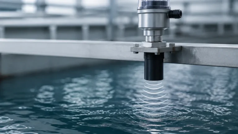
3. Ultrasonic Gap Switches
These sensors utilize two piezoelectric crystals separated by a small gap. One crystal acts as a transmitter and the other as a receiver.
* Operation: When the gap is filled with air, the ultrasonic signal is attenuated and does not reach the receiver. When liquid fills the gap, the signal is transmitted across.
* Horizontal Specifics: These are ideal for clean liquids and are less sensitive to coating than capacitance probes. In horizontal mounts, the gap must be oriented vertically to prevent air bubbles from becoming trapped, which would cause a false "dry" signal.
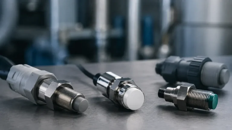
4. Capacitance Level Switches
Capacitance switches measure the change in electrical capacitance between the sensor probe and the tank wall (or a reference electrode).
* Operation: Since liquids have a higher dielectric constant than air, the presence of the medium increases the measured capacitance, triggering the switch.
* Horizontal Specifics: Horizontal capacitance probes are often shorter than vertical ones. They are suitable for both liquids and solids, though they require calibration to the specific dielectric constant of the material.
Practical Selection Criteria
Choosing a Level Switches solution for horizontal mounting involves evaluating several environmental and process variables. The following table summarizes the primary considerations for common technologies.
Selection Comparison Table
| Technology | Media Type | Max Temperature | Max Pressure | Best For | Limitations |
| :— | :— | :— | :— | :— | :— |
| Magnetic Float | Clean, low-viscosity liquids | Up to 200°C | Up to 40 bar | Simple, low-cost automation | Moving parts; prone to clogging in dirty media |
| Tuning Fork | Liquids, slurries, powders | Up to 250°C | Up to 64 bar | Overfill protection; high reliability | Higher initial cost; sensitive to very high viscosity |
| Capacitance | Liquids, solids, granules | Up to 200°C+ | Up to 100 bar | High pressure/temp; non-conductive media | Requires calibration; sensitive to coating/build-up |
| Ultrasonic Gap | Clean liquids | Up to 150°C | Up to 40 bar | Aerated liquids; foaming applications | Not for high-viscosity or crystallizing liquids |
Media Density and Viscosity
For float-based level switch horizontal installations, the liquid's specific gravity (SG) is the most critical factor. The float must be less dense than the liquid to maintain buoyancy. Most standard floats require an SG of at least 0.7. For high-viscosity liquids, vibrating forks or capacitance sensors are preferred, as mechanical floats may become stuck or sluggish in their movement.
Chemical Compatibility
The wetted parts—the components in direct contact with the media—must be resistant to corrosion. Common materials include Stainless Steel (304, 316L), Hastelloy, and plastics like PVC, PP, or PVDF. For aggressive chemicals, PTFE-coated probes are often specified.
Installation Guidelines for Horizontal Switches
Proper installation is paramount to ensuring the long-term reliability of a horizontal level sensor. Errors in mounting can lead to false positives, mechanical failure, or leaks.
1. Nozzle Length and Diameter
When mounting a switch through a nozzle (a pipe extension from the tank wall), the length of the nozzle must not interfere with the sensor's operation. For float switches, the nozzle must be wide enough to allow the float to pivot freely. For tuning forks, the tines must extend fully into the vessel to ensure they are not shielded by the nozzle, which could trap liquid and prevent the sensor from resetting.
2. Orientation and Drainage
* Tuning Forks: As mentioned, tines should be oriented vertically. This allows gravity to pull liquid off the tines as the level recedes.
* Float Switches: The pivot point should be horizontal. If the switch is rotated, the float may not move correctly under buoyancy.
* Conduit Entry: Always point the cable entry or conduit connection downward. This creates a "drip loop" that prevents moisture from traveling along the cable and entering the electronic housing.
3. Avoiding Turbulence and Obstructions
Avoid installing level switches directly in the path of an inlet flow or near an agitator. The mechanical force of the liquid hitting the sensor can cause premature wear or false switching. If a turbulent area is unavoidable, a stilling well or a protective baffle should be installed to shield the sensor.
4. Sealing and Threading
Most horizontal switches use NPT (National Pipe Taper) or G (Parallel) threads. Ensure that appropriate thread sealant (like PTFE tape or pipe dope) is used for NPT threads. For G threads, a flat gasket or O-ring is required to create a pressure-tight seal against the tank boss.
Limitations and Common Risks
While horizontal mounting is versatile, it is not without risks. Engineers should be aware of the following potential issues:
* Build-up and Scaling: In applications involving wastewater or lime slurry, material can build up on the sensor. For horizontal mounts, this build-up can weigh down a float arm or bridge the gap of an ultrasonic sensor, leading to permanent "on" states.
* Mechanical Stress: In high-pressure vessels, the side-mounted nozzle and the switch itself are subject to significant cantilever stress. Ensure the mounting connection is rated for the vessel's maximum operating pressure.
* Dead Zones: Every switch has a small "dead zone" where it cannot accurately detect liquid. In horizontal mounts, this is usually the distance from the tank wall to the active sensing element. This must be accounted for in the control logic.
Maintenance and Troubleshooting
Regular maintenance ensures that the level switch horizontal remains functional throughout its service life.
1. Visual Inspection: Check for signs of leakage around the threads or flange. Inspect the housing for corrosion or moisture ingress.
2. Functional Test: Periodically manually trip the switch (if accessible) or raise the liquid level to verify that the output relay triggers the intended alarm or pump control.
3. Cleaning: For media that tends to coat, remove the sensor annually to clean the probe or float mechanism. Use a soft brush or solvent that is compatible with the sensor material.
Frequently Asked Questions (FAQs)
Q: Can a horizontal level switch be used for solids?
A: Yes, but not all technologies are suitable. Capacitance and vibrating rod (a variation of the tuning fork) switches are commonly used for horizontal detection of powders and granules in silos. Float switches are strictly for liquids.
Q: What is the advantage of a horizontal switch over a vertical one?
A: The primary advantage is accessibility. If a tank is 10 meters tall, installing and maintaining a switch at the top is difficult. A horizontal switch can be placed at the exact height required (e.g., 2 meters from the bottom) and accessed via a ladder or platform.
Q: How do I prevent false triggers from foam?
A: Tuning fork switches are excellent at ignoring foam and only detecting the actual liquid level. If using a float switch, the foam must be light enough that it does not displace the float, though heavy, dense foam can occasionally cause issues.
Q: What is the maximum pressure for a side-mounted float switch?
A: This depends on the float material and thickness. Standard stainless steel floats can typically handle up to 30 or 40 bar (approx. 435 to 580 psi). High-pressure versions are available for specialized applications.
By carefully considering the measurement principle and following rigorous installation standards, a level switch horizontal configuration provides a robust and accessible solution for point-level monitoring in diverse industrial environments.