Voltage Level Switch
Voltage Level Switch
In industrial automation and process control, the term voltage level switch refers to point-level detection devices characterized by their electrical supply requirements and output signal types. While the primary function of any level switch is to detect the presence or absence of a medium at a specific height, the electrical interface—the voltage—determines how the device integrates into a broader control system, such as a Programmable Logic Controller (PLC) or a Distributed Control System (DCS). Selecting the correct voltage level switch involves balancing the physical sensing technology with the electrical infrastructure of the facility.
Industrial level measurement requires high reliability, especially when switches are used for overfill protection or pump control. Understanding the relationship between the sensing principle and the electrical output is essential for engineers and procurement specialists. This guide explores the technical specifications, measurement principles, and selection criteria for level switches operating across various voltage ranges.
Measurement Principles of Level Switches
Before selecting a voltage level switch based on its electrical characteristics, it is necessary to understand the physical sensing mechanism. The technology must be compatible with the process medium (liquid, powder, or granulate) and the tank environment.
Vibrating Tuning Fork
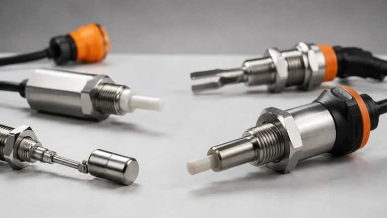
This technology utilizes a piezoelectric crystal to vibrate a metal fork at its natural frequency. When the fork is immersed in a medium, the frequency shifts. The internal electronics detect this change and trigger the output. These switches are highly versatile and are often available as a DC voltage level switch for PLC integration or an AC version for direct load switching.
Float and Magnetic Switches
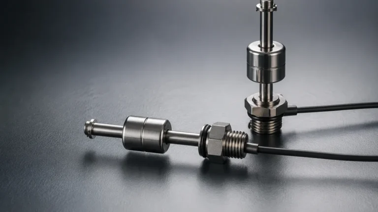
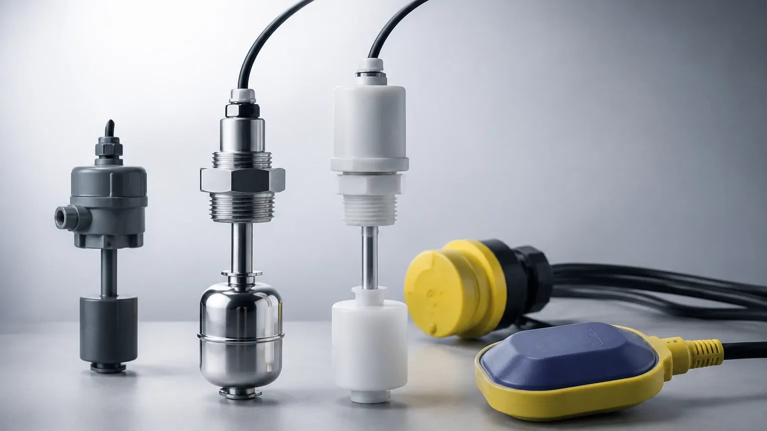
Float switches operate on the principle of buoyancy. A float containing a magnet moves with the liquid level, actuating a reed switch or a microswitch inside the stem. Because they are often purely mechanical in their switching action, they can handle a wide range of voltages, provided the current limits of the internal contacts are respected.
Capacitive Level Switches
Capacitive sensors measure the change in electrical capacitance between the sensor probe and the tank wall (or a reference electrode). When the medium covers the probe, the dielectric constant changes, altering the capacitance. These devices require a stable power supply to operate the internal oscillator and sensing circuitry, typically 24V DC.
Ultrasonic and Optical Switches
Ultrasonic switches use high-frequency sound waves to detect the presence of a medium in a gap, while optical switches use infrared light refraction. Both technologies are solid-state, meaning they have no moving parts. They typically operate on low-voltage DC power and provide a transistor-based voltage output.
Electrical Configurations and Output Types
The "voltage" aspect of a Level Switches usually refers to two distinct parameters: the input supply voltage and the output switching voltage.
Supply Voltage Categories
1. Low Voltage DC (12V – 36V DC): This is the most common configuration in modern industrial environments. It is safe for technicians and integrates directly with PLC input cards. Most 24V DC switches use PNP or NPN transistor outputs.
2. High Voltage AC (85V – 265V AC): Used in older facilities or applications where the switch must directly control a motor starter or a high-power solenoid without an intervening relay. These are often referred to as universal voltage switches.
Output Logic and Wiring
* PNP (Sourcing): The switch connects the output to the positive supply voltage when triggered. This is standard in European industrial markets.
* NPN (Sinking): The switch connects the output to the negative/common terminal. This is more common in Asian markets and certain specialized electronics.
* Relay Contact (SPDT/DPDT): The switch provides a dry contact (volt-free). This allows the user to switch a different voltage than the supply voltage, providing excellent isolation.
* Two-Wire AC/DC: These switches operate in series with the load, similar to a standard light switch. They have a small leakage current when "off" to power the internal sensor.
Selection Criteria for Voltage Level Switches
Choosing the right instrument requires a technical evaluation of both the process and the electrical system. The following table summarizes common technologies and their typical voltage characteristics.
Technical Selection Table
| Technology | Typical Supply Voltage | Output Type | Best Application |
| :— | :— | :— | :— |
| Tuning Fork | 20-250V AC/DC | Relay or PNP/NPN | General purpose liquids/solids |
| Float Switch | N/A (Passive) | Reed/Microswitch | Clean liquids, non-coating |
| Capacitive | 12-36V DC | PNP/NPN | High-viscosity or corrosive liquids |
| Ultrasonic Gap | 18-30V DC | Relay or 4-20mA | Aerated liquids, chemical tanks |
| Rotary Paddle | 110/220V AC | Microswitch | Bulk solids, silos, and hoppers |
Key Considerations
* Load Requirements: If the switch is driving a high-current device like a pump motor, a relay output is mandatory. For signal-level communication with a PLC, a transistor output (PNP) is more reliable and has a longer service life.
* Response Time: Solid-state voltage level switches (tuning fork, capacitive) respond in milliseconds, whereas mechanical floats or rotary paddles may have a delay due to physical movement.
* Fail-Safe Modes: High-level alarms should be configured as "normally closed" (NC) so that a power failure or cable break triggers the alarm, ensuring safety.
Installation and Wiring Guidelines
Correct installation is vital to ensure that the voltage level switch operates accurately and safely. Electrical noise and improper grounding are the most common causes of switch failure in industrial settings.
Wiring Best Practices
1. Cable Shielding: For DC switches located near high-frequency drives (VFDs) or large motors, use shielded cables to prevent electromagnetic interference (EMI) from causing false triggers.
2. Voltage Drop: Ensure the cable gauge is sufficient for the distance. While 24V DC is standard, a long cable run (over 100 meters) can result in a voltage drop that prevents the switch from functioning correctly.
3. Conduit Seals: In applications involving temperature fluctuations, moisture can condense inside conduits and enter the switch housing. Use proper cable glands (IP66 or higher) and drip loops.
4. Grounding: Ensure the instrument housing is grounded according to local electrical codes (e.g., NEC or IEC standards) to protect against surge voltages.
Mechanical Mounting
* Avoid Turbulence: Do not install switches directly in the path of a fill pipe. The force of the incoming liquid can damage floats or cause false resonance in tuning forks.
* Orientation: Some switches are designed for vertical mounting only (top-down), while others can be installed horizontally (side-wall). Check the manufacturer specifications for the specific model.
Limitations and Operational Risks
While voltage level switches are robust, they are not without limitations. Engineers must account for the following risks during the design phase:
* Contact Pitting: In mechanical switches (floats/rotary), switching inductive loads like solenoids can cause arcing, which pits the contacts and leads to premature failure. Using an external RC snubber or diode can mitigate this.
* Coating and Buildup: Capacitive and tuning fork switches can fail if the medium is highly viscous and leaves a thick coating on the sensor. In these cases, a switch with "active shield" technology or a specific frequency adjustment is required.
* Ambient Temperature: The electronics inside a voltage level switch are typically rated for up to 70°C or 80°C. If the process temperature is higher (e.g., 150°C), a remote-mounted electronic housing or a high-temperature extension neck must be used.
* Hazardous Areas: In environments with explosive gases or dust, a standard voltage level switch cannot be used. Instead, an intrinsically safe (Ex i) or flameproof (Ex d) version is required, often necessitating the use of an isolation barrier in the control cabinet.
Frequently Asked Questions (FAQs)
Q: Can I use a 24V DC switch with a 110V AC control circuit?
No, you cannot connect a DC transistor output directly to an AC circuit. You must use an intermediate relay. The 24V DC switch triggers the relay coil, and the relay's dry contacts switch the 110V AC load.
Q: What is the difference between a 2-wire and a 3-wire DC switch?
A 3-wire switch has dedicated wires for power (+ and -) and a separate wire for the output signal. A 2-wire switch operates in series with the load. 3-wire switches are generally more stable and have no leakage current issues.
Q: How do I test a voltage level switch in the field?
For a PNP switch, use a multimeter to measure the voltage between the output wire and the common (negative) wire. When the switch is triggered, you should see a voltage nearly equal to the supply voltage. For a relay output, use the continuity setting to check if the contacts open and close.
Q: Why is my switch flickering on and off when the level is near the setpoint?
This is often caused by surface turbulence or waves. Many electronic level switches have a built-in delay (typically 1 to 5 seconds) that can be adjusted to ignore momentary changes in level. If the switch is mechanical, a stilling well may be required.
Conclusion
The selection of a voltage level switch is a critical decision that bridges the gap between mechanical process requirements and electrical control logic. By understanding the measurement principles—whether vibrating, buoyant, or capacitive—and matching them with the appropriate voltage supply and output type, facilities can ensure long-term operational stability. Manufacturers like Welk provide a wide range of Level Switches designed to meet these diverse industrial needs, offering solutions that range from simple float switches to advanced tuning fork sensors for complex applications.